Pulse width modulation (PWM) is a technique in which the duty cycle of a periodic signal is modified, either to transmit information over a communication channel or to control the amount of energy sent to a load. One of its main uses is the control of power supplies or motors.
The switching frequency in a PWM signal will depend on the application in which it is implemented.
- Around 120Hz for lighting
- From kHz to tens of kHz for motor control
- Hundreds of kHz in audio amplifiers and power supplies
The term "Duty Cycle" refers to the percentage of its period during which the signal is "on." Most of the time, the duty cycle is represented as a percentage, with 0% being a completely off signal and 100% being a completely on signal.
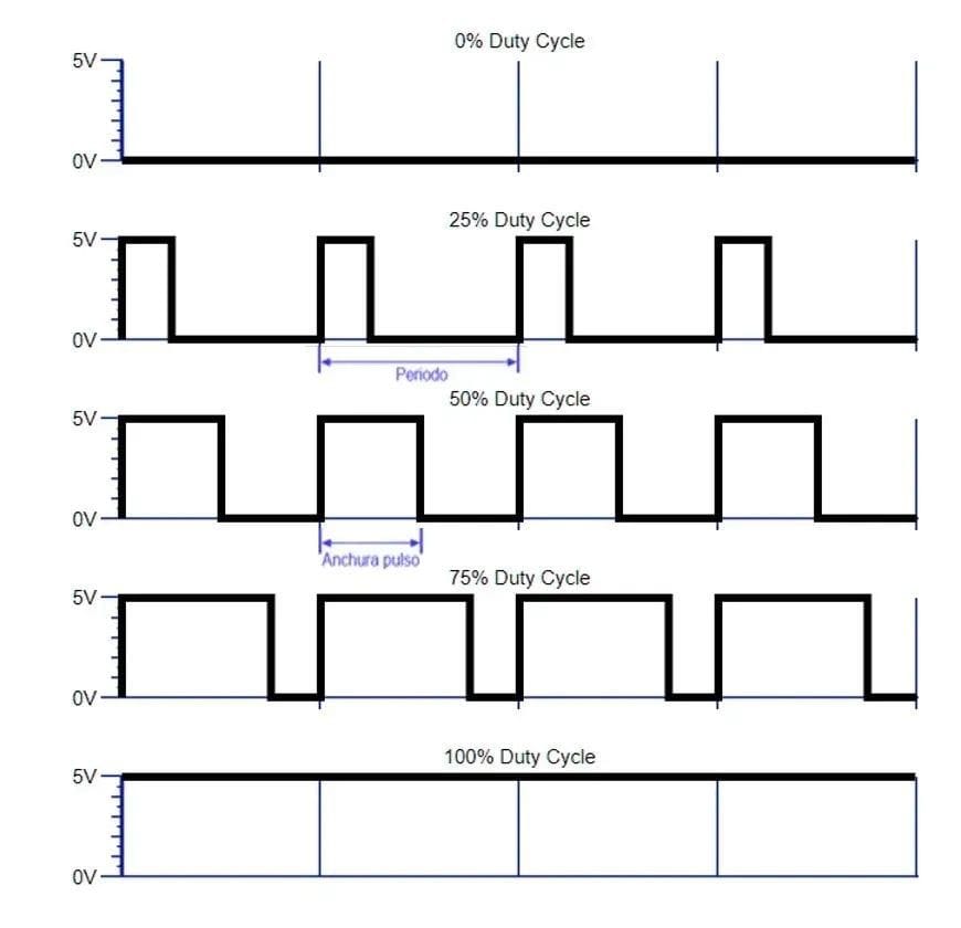
The main advantage of PWM is that the energy loss during signal switching is very small. When the signal is at a low level, there is practically no current consumption, and when the signal switches to an active (high) state, there is almost no energy loss. Energy is only consumed from the power source for the duration of the duty cycle.
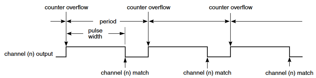
Edge-Aligned PWM mode
In this PWM generation mode, the first cycle of the signal starts with the counter at the value of zero or at overflow, and the polarity change occurs at the value set in the channel that will produce the PWM. Again, the polarity change occurs at the overflow of the base counter.
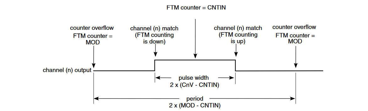
Center-Aligned PWM mode
Center-aligned means that the base counter should continuously count up and then down. The first cycle of the signal will start with the counter counting up from zero, and the polarity change occurs when the counter reaches the programmed maximum. A new cycle will begin when the counter reaches zero again and starts over.
STM32G0x1 TIM Peripheral
The microcontrollers in the STM32G0 family do not have an individual PWM module. PWM signals are generated using the TIM timers of the microcontroller along with their channels. While the frequency of the signal is generated by the timers' count, the duty cycle is set by the capture/compare modules of each channel. The number of PWM signals for each timer will depend on how many channels it has. All PWM signals from the same timer will share the same frequency.
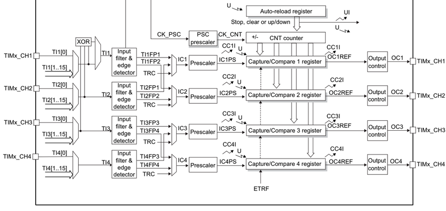
The frequency of a PWM signal is determined by the value in the timer's auto-reload register, along with the prescaler values and the frequency that drives it. The duty cycle is set by the value in the capture/compare register, and its value cannot exceed the value in the auto-reload register.
STMicroelectronics Official Video Training]
STM32CubeG0 PWM HAL driver
The code to control the digital ports is located in the following libraries.
stm32g0xx_hal_tim.hstm32g0xx_hal_tim.cstm32g0xx_hal_tim_ex.hstm32g0xx_hal_tim_ex.c
In the stm32g0xx_hal_conf.h file, it is necessary to uncomment the define.
#define HAL_TIM_MODULE_ENABLED
Functions
HAL_StatusTypeDef HAL_TIM_PWM_Init(TIM_HandleTypeDef *htim);
HAL_StatusTypeDef HAL_TIM_PWM_DeInit(TIM_HandleTypeDef *htim);
void HAL_TIM_PWM_MspInit(TIM_HandleTypeDef *htim);
void HAL_TIM_PWM_MspDeInit(TIM_HandleTypeDef *htim);
/* Blocking mode: Polling */
HAL_StatusTypeDef HAL_TIM_PWM_Start(TIM_HandleTypeDef *htim, uint32_t Channel);
HAL_StatusTypeDef HAL_TIM_PWM_Stop(TIM_HandleTypeDef *htim, uint32_t Channel);
/* Non-Blocking mode: Interrupt */
HAL_StatusTypeDef HAL_TIM_PWM_Start_IT(TIM_HandleTypeDef *htim, uint32_t Channel);
HAL_StatusTypeDef HAL_TIM_PWM_Stop_IT(TIM_HandleTypeDef *htim, uint32_t Channel);
/* Non-Blocking mode: DMA */
HAL_StatusTypeDef HAL_TIM_PWM_Start_DMA(TIM_HandleTypeDef *htim, uint32_t Channel, const uint32_t *pData,uint16_t Length);
HAL_StatusTypeDef HAL_TIM_PWM_Stop_DMA(TIM_HandleTypeDef *htim, uint32_t Channel);
Configuration Structure
typedef struct
{
    uint32_t OCMode;        /*!< Specifies the TIM mode.*/
    uint32_t Pulse;         /*!< Specifies the pulse value to be loaded into the Capture Compare Register.*/
    uint32_t OCPolarity;    /*!< Specifies the output polarity. */
    uint32_t OCNPolarity;   /*!< Specifies the complementary output polarity.*/
    uint32_t OCFastMode;    /*!< Specifies the Fast mode state. */
    uint32_t OCIdleState;   /*!< Specifies the TIM Output Compare pin state during Idle state. */
    uint32_t OCNIdleState;  /*!< Specifies the TIM Output Compare pin state during Idle state. */
} TIM_OC_InitTypeDef;
Code Snippets
- PWM: Single Signal with 50% duty cycle
- PWM: Three signals at different duty cycles
- PWM: Single signal pulse variation
- PWM: Complementary signals
Exercises
- Write a program to generate two PWM channels but using two different timers, see which pins are available with TIM functionality
- Generate two complement PWM signal with dead time insertion of around 1% of the period of the signal
- The on board buzzer works with a 12KHz signal, beep the buzzer every time a button is pressed and then stop the buzzer when the same button has been pressed again
- Use a potentiometer to variate the PWM duty cycle connected to RGB led from 10% to 90% in steps of 10%
- Add the second pot to control the duty cycle in the red RGB led. plus one button to enable an disable both PWM signals
- Using one single pot control the three RGB leds one at a time, you will need to use the buttons, each of them will active one color at a time, meaning if we press button 1 only color blue PWM is active, but if we press the button 2 only color red will be active and so on, use the on board leds to indicate which color is currently controlled by the pot. You better make use of the scheduler for this one