This example shows how to use Queues as a communication method between ISR and Task.
In this example, we going to control the status of an LED (ON/OFF) using a Queue to pass the status to the corresponding Hal function to change the pin state.
Using a simple interrupt to read 2 buttons, one button will turn on the LED and the other one must turn off the LED. The callback interrupt detects which button was pressed and sends the respective message to the Queue, a task registered must read the Queue data and change the status of the LED.
In a Interrupt, function callback must be short and fast. Therefore, add the function xQueueSendFromISR() to prevent that ISR funtion blocks when is sending the data to queue.
Code Example:
#include "bsp.h"

static void vTask( void *parameters );      /* Task to turn ON or OFF the LED */

QueueHandle_t QueueLEDstatus;

int main( void )
{
    HAL_Init( );
    /*enable RTT and system view*/
    SEGGER_SYSVIEW_Conf( );
    SEGGER_SYSVIEW_Start( );

    HAL_NVIC_SetPriority( EXTI4_15_IRQn, 2, 0 );                    /* Set priority of interrupts Buttons */
    HAL_NVIC_EnableIRQ( EXTI4_15_IRQn );                            /* Enable the extenal interrupts */

    QueueLEDstatus = xQueueCreate( 2, sizeof(uint16_t) );           /* Create the Queue to store a data of 16 bits */

    xTaskCreate( vTask, "TaskControlLED", 128u, NULL, 1u, NULL );   /* Register a Task */

    vTaskStartScheduler( );                                         /* initilize the kernel */

    return 0u;
}

static void vTask( void *parameters )
{
    UNUSED( parameters );
    uint16_t dataRead;                                      /* Variable to store data of Queue */

    for( ;; )
    {
        xQueueReceive( QueueLEDstatus, &dataRead, 0 );      /* Read the data of the Queue */
        HAL_GPIO_WritePin( GPIOC, GPIO_PIN_0, dataRead );   /* Change the LED Status */
        SEGGER_SYSVIEW_PrintfHost( "LED %d", dataRead );    /* Print in Terminal the LED Status */

        vTaskDelay(1 / portTICK_PERIOD_MS);               /* Periodicity of Task */
    }
}

void HAL_GPIO_EXTI_Rising_Callback( uint16_t GPIO_Pin )     /* Callback of interrupt */
{
    uint16_t LEDstatus;                                 /* Variable to store data to be send to Queue */
    if(GPIO_PIN_15 == GPIO_Pin)                         /* Check wich button is pressed */
    {
        LEDstatus = GPIO_PIN_SET;                       /* Update data to be send */
    }
    else if(GPIO_PIN_7 == GPIO_Pin)                     /* Check wich button is pressed */
    {
        LEDstatus = GPIO_PIN_RESET;                     /* Update data to be send */
    }
    xQueueSendFromISR( QueueLEDstatus, &LEDstatus, 0 ); /* Send data to Queue Without block ISR function */

    portEND_SWITCHING_ISR( pdFALSE );                   /* Change context */
}
SystemView output:
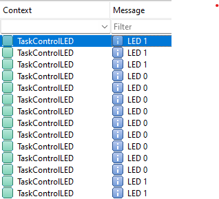
Terminal will show the LED's behavior, Queue is sent during the interruption and the task should read it and update the pin state.
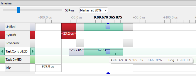
Timeline:
|
Now in timeline, we can observe that only one task is executing, which is in charge of updating the pin state according the Queue message received. |
|
|
when a button is pressed, the Interrupt executes to send a message to change the LED state and turn it on. |
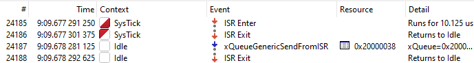
|
|
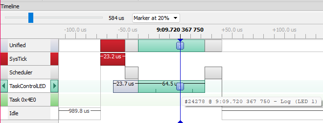
Finally, when task "vTask" executes again the Queue contains the message of the interruption.
|  |