Direct Memory Access (DMA), is a hardware-controlled data transfer used to perform data transfer between memory-mapped, peripherals and/or memories, without handling this data by the processor. It makes the transaction more efficient since the task is not performed by the CPU, therefore processor time is saved. The external device generates address and control signals that are required to control data transfer. External devices also allow peripheral devices to directly access memory. The external device which controls the data transfer is called the DMA controller.

The DMA sharing the AHB system bus with other system masters. The bus Matrix implements round-robin scheduling. DMA requests may stop the CPU access to the system bus for a number of cycles when the CPU and DMA target the same destination. According to the DMA configuration, the AHB slave interface the controller can arbitrate channels and associated received requests. The DMA also schedules the data transfer over the single AHB port master. The DMA controller generates an interrupt per channel to the interrupt controller.
DMA Channels:
DMA channel is programmed at block transfer level. Each channel uses the DMA transfer Handler to configure peripheral register located in a fixed address, and memory address. The amount of data items to send is programmable. The register that contains the amount of data to send is decremented each transfer.
Data Sizes:
We can choose between 3 different sizes to transfer (byte, half-word, word) 8, 16, and 32 Bits respectively. The transfer sizes of a single data to the peripheral and memory are programmable through the PSIZE[1:0] and MSIZE[1:0] fields of the DMA_CCRx register.
Pointer increment:
The peripheral and memory address may automatically increment after each transfer, depending on the PINC and MINC bits programmed. If the increment mode is enabled, the address of the next transfer is the address of the previous one incremented by 1, 2, or 4, depending the data size defined.
Normal and circular mode:
If channel x is configured as non-circular mode (Normal mode), no DMA request is served after the last data transfer and the channel must be disabled. If channel x is disabled, the DMA registers are not reset and retain the initial values programmed during the channel configuration phase. In a circular mode after the last transfer, the DMA channel register is automatically reloaded with the initially programmed values. In this mode, DMA requests must be served after each data transfer. The circular mode is available to handle circular buffers and continuous data flows (such as ADC scan mode).
The circular mode must not be used in memory-to-memory mode.
DMA Arbitration:
The DMA Arbiter selects the channel to be executed and manages the priority between the different channels. For example, if 2 requests simultaneously are sent to the arbiter, this going to execute only once a time, after finishing the transaction, the next channel is going to be executed, this order depends on the number of channels, channel 0 has the high priority and channel 7 have the low priority. The priorities are managed in two stages:
- Software: priority of each channel is configured in the DMA_CCRx register, to one of the four different levels:
- very high
- high
- medium
- low
- Hardware: if two requests have the same software priority level, the channel with the lowest index gets priority. For example, channel 2 gets priority over channel 4.
When a channel is programmed to transfer in memory to memory mode, re-arbitration is considered passing to the next channel with the highest priority which may be of lower priority than the memory-to-memory channel.
DMAMUX
Each channel has a software configurable selection of peripherals. On legacy products, the channel has a restricted request for peripherals in a given channel. The DMAMUX adds more flexibility, it offers fully configurable routing of any DMA request from a given peripheral to any DMA controller or DMA channel. The routing function is ensured by a programmable multi-channel DMA request line multiplexer. Each channel selects a unique DMA request line to forward (unconditionally or synchronously) to the associated DMA controller channel. This allows the DMA requests to be managed with high flexibility, maximizing the number of DMA requests that run concurrently.
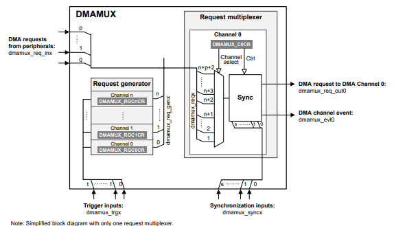
The DMAMUX is composed mainly of 2 components, Request generator and request multiplexer. The request generator allows DMA request generation on interrupt signals or events.
- input:
- dmamux_trgx: trigger event input to request generator sub-block.
- output:
- dmamux_req_genx: DMA request from the request generator sub-block to the DMAMUX request multiplexer channels.
Request generator is instantiated once by DMAMUX. Contains N channels capable of generating DMA requests.
The request multiplexer includes a synchronization unit per channel with inputs and outputs:
- inputs:
- dmamux_reqx: DMA request from a peripheral (dmamux_req_inx) or from the request generator (dmamux_req_genx), this request is generated by a trigger input.
- dmamux_syncx: optional synchronization event.
- outputs:
- dmamux_req_outx: request forwarded to the input to output.
- dmamux_evtx: optional generated event, that can be used to trigger or synchronize other DMAMUX channels.
Resuming DMAMUX is configured when DMA is initialized, instead of a normal DMA initialization to configure the DMA request and channel selected, but also DMAMUX can be configured to set another request when an interruption or event occurs.
STMicroelectronics Official Video Training
STM32CubeG0 DMA HAL driver
The code for controlling the direct memory access transfer (DMA) is located in the following libraries.
stm32g0xx_hal_dma.hstm32g0xx_hal_dma.cstm32g0xx_hal_dma_ex.hstm32g0xx_hal_dma_ex.c
In the file stm32g0xx_hal_conf.h you should uncomment the define macro.
#define HAL_DMA_MODULE_ENABLED
Functions
/* Initialization and de-initialization functions *****************************/
HAL_StatusTypeDef HAL_DMA_Init(DMA_HandleTypeDef *hdma);
HAL_StatusTypeDef HAL_DMA_DeInit(DMA_HandleTypeDef *hdma);
/* IO operation functions *****************************************************/
HAL_StatusTypeDef HAL_DMA_Start(DMA_HandleTypeDef *hdma, uint32_t SrcAddress, uint32_t DstAddress, uint32_t DataLength);
HAL_StatusTypeDef HAL_DMA_Start_IT(DMA_HandleTypeDef *hdma, uint32_t SrcAddress, uint32_t DstAddress, uint32_t DataLength);
HAL_StatusTypeDef HAL_DMA_Abort(DMA_HandleTypeDef *hdma);
HAL_StatusTypeDef HAL_DMA_Abort_IT(DMA_HandleTypeDef *hdma);
HAL_StatusTypeDef HAL_DMA_PollForTransfer(DMA_HandleTypeDef *hdma, HAL_DMA_LevelCompleteTypeDef CompleteLevel, uint32_t Timeout);
void HAL_DMA_IRQHandler(DMA_HandleTypeDef *hdma);
HAL_StatusTypeDef HAL_DMA_RegisterCallback(DMA_HandleTypeDef *hdma, HAL_DMA_CallbackIDTypeDef CallbackID, void (* pCallback)(DMA_HandleTypeDef *_hdma));
HAL_StatusTypeDef HAL_DMA_UnRegisterCallback(DMA_HandleTypeDef *hdma, HAL_DMA_CallbackIDTypeDef CallbackID);
/* Peripheral State and Error functions ***************************************/
HAL_DMA_StateTypeDef HAL_DMA_GetState(DMA_HandleTypeDef *hdma);
uint32_t             HAL_DMA_GetError(DMA_HandleTypeDef *hdma);
Extra Functions
/* ------------------------- REQUEST -----------------------------------------*/
HAL_StatusTypeDef HAL_DMAEx_ConfigMuxRequestGenerator(DMA_HandleTypeDef *hdma, HAL_DMA_MuxRequestGeneratorConfigTypeDef *pRequestGeneratorConfig);
HAL_StatusTypeDef HAL_DMAEx_EnableMuxRequestGenerator(DMA_HandleTypeDef *hdma);
HAL_StatusTypeDef HAL_DMAEx_DisableMuxRequestGenerator(DMA_HandleTypeDef *hdma);
/* ------------------------- SYNCHRO -----------------------------------------*/
HAL_StatusTypeDef HAL_DMAEx_ConfigMuxSync(DMA_HandleTypeDef *hdma, HAL_DMA_MuxSyncConfigTypeDef *pSyncConfig);
void              HAL_DMAEx_MUX_IRQHandler(DMA_HandleTypeDef *hdma);
Code Snippets
- DMA: Memory to Memory
- DMA: Memory to Memory with Int.
- DMA: Two channels Memory to Memory
- DMA: ADC1 Peripheral to Memory (1 channel)
- DMA: ADC1 Timer triggered DMA
- DMA: Memory to PWM Peripheral
- DMA: Configuring DMAMUX to trigger a signal using a button
Exercises:
- Read two ADC channels in one shot mode and transfer both measurements to a given RAM address one after the other using one DMA channels
- Modify the previous exercise to read up to five channels, single mode and DMA transfer using only one channel