The CAN bus is a multi-master data transmission protocol based on messages and specifically designed for automotive applications, but now it is also used in other areas such as aerospace, industrial automation, and medical equipment. It allows different components to communicate on a network data bus using one or two cables, with speeds of up to 1 Mbps. It uses the concept of broadcasting, which means that all nodes can "listen" to all transmissions. However, the CAN controller has local filters that allow each node to react only to messages of its interest.
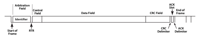
A CAN 2.0A "standard CAN" data frame consists mainly of the following parts:
- Arbitration Field: This field consists of 11 bits for the message identifier and the RTR bit. The RTR bit is dominant (0) for data frames and recessive (1) for remote request frames.
- Control Field: This field includes the Identifier Extension bit (IDE), which must be dominant (0) for 11-bit identifiers; a reserved bit for potential future protocol updates; and four bits for Data Length Code (DLC) that indicate the number of data bytes in the message, ranging from 0 to 8 bytes.
- Data Field: This field contains 0 to 8 bytes of data.
- CRC Field: This field consists of 15 bits for error checking and detection, serving as a code to verify the correct transmission of data. It also includes the CRC delimiter bit.
- ACK Field: The transmitter sends a recessive (1), and any receiver sends dominant (0). If this bit is dominant, it indicates that at least one other device received the message. Otherwise, the transmitter re-transmits the message.
There are literally hundred of videos in the intern explaining how a CAN bus work, that is why i think it is a better idea to focus on the things you are not going to find s so easily out there. My favorite two are CAN Bus explained and Kvaser CAN Protocol Course, but there are many more
STM32G0x1 FDCAN Peripheral
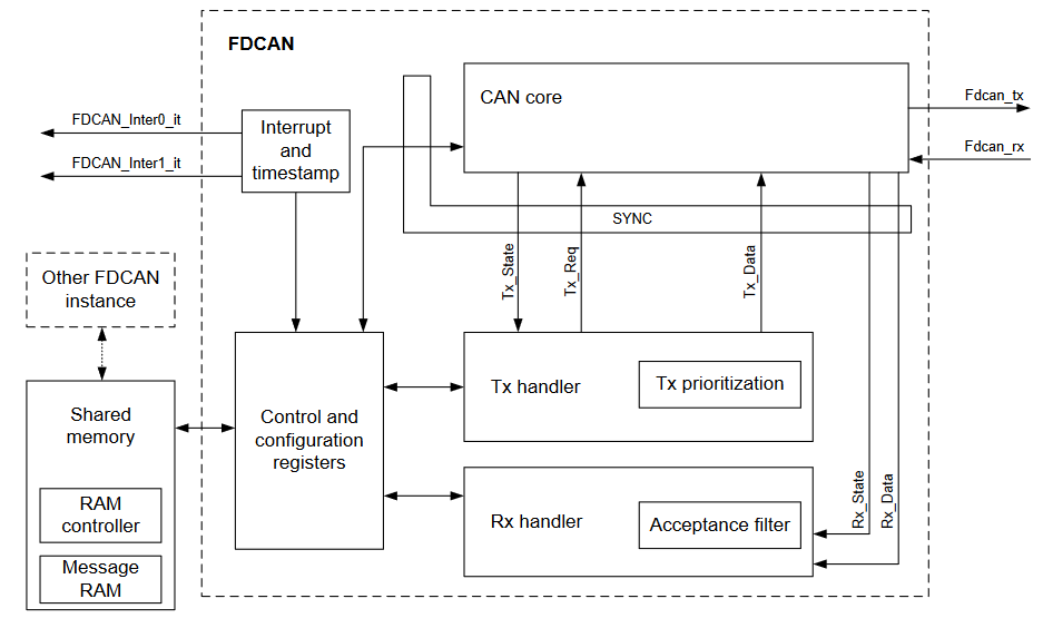
The controller area network (CAN) subsystem (see Figure 392) consists of one CAN module, a shared message RAM and a configuration block. Refer to the memory map for the base address of each of these parts. The modules (FDCAN) are compliant with ISO 11898-1: 2015 (CAN protocol specification version 2.0 part A, B) and CAN FD protocol specification version 1.0. A 0.8-Kbyte message RAM per FDCAN instance implements filters, receive FIFOs, transmit event FIFOs and transmit FIFOs.
Main features:
- Conform with CAN protocol version 2.0 part A, B and ISO 11898-1: 2015, -4
- CAN FD with maximum 64 data bytes supported
- CAN error logging
- AUTOSAR and J1939 support
- Improved acceptance filtering
- Two Receive FIFOs of three payloads each (up to 64 Bytes per payload)
- Separate signaling on reception of High priority messages
- Configurable Transmit FIFO / queue of three payload (up to 64 Bytes per payload)
- Transmit Event FIFO
- Programmable loop-back test mode
- Maskable module interrupts
- Two clock domains: APB bus interface and CAN core kernel clock
- Power down support
The FDCAN is a quiet interesting peripheral that required a much extend explanation and exploration you find further and extend information on the following ST application note: AN5348 - Introduction to FDCAN peripherals for STM32 also Bit Timing Calculation and Stm32g0 FDCAN Tx buffer operation
STMicroelectronics Official Video Training
Video makes reference to STM32L5 Mcu line but it is perfectly applicable for the STM32G0 family since the peripheral are exactly the same
STM32CubeG0 FDCAN HAL driver
The code to control the digital ports is located in the following libraries.
stm32g0xx_hal_fdcan.hstm32g0xx_hal_fdcan.c
In the stm32g0xx_hal_conf.h file, it is necessary to uncomment the define.
#define HAL_FDCAN_MODULE_ENABLED
Functions
/* Initialization and de-initialization functions *****************************/
HAL_StatusTypeDef HAL_FDCAN_Init(FDCAN_HandleTypeDef *hfdcan);
HAL_StatusTypeDef HAL_FDCAN_DeInit(FDCAN_HandleTypeDef *hfdcan);
void              HAL_FDCAN_MspInit(FDCAN_HandleTypeDef *hfdcan);
void              HAL_FDCAN_MspDeInit(FDCAN_HandleTypeDef *hfdcan);
/* Configuration functions ****************************************************/
HAL_StatusTypeDef HAL_FDCAN_ConfigFilter(FDCAN_HandleTypeDef *hfdcan, FDCAN_FilterTypeDef *sFilterConfig);
HAL_StatusTypeDef HAL_FDCAN_ConfigGlobalFilter(FDCAN_HandleTypeDef *hfdcan, uint32_t NonMatchingStd, uint32_t NonMatchingExt, uint32_t RejectRemoteStd, uint32_t RejectRemoteExt);
HAL_StatusTypeDef HAL_FDCAN_ConfigExtendedIdMask(FDCAN_HandleTypeDef *hfdcan, uint32_t Mask);
HAL_StatusTypeDef HAL_FDCAN_ConfigRxFifoOverwrite(FDCAN_HandleTypeDef *hfdcan, uint32_t RxFifo, uint32_t OperationMode);
/* Control functions **********************************************************/
HAL_StatusTypeDef HAL_FDCAN_Start(FDCAN_HandleTypeDef *hfdcan);
HAL_StatusTypeDef HAL_FDCAN_Stop(FDCAN_HandleTypeDef *hfdcan);
HAL_StatusTypeDef HAL_FDCAN_AddMessageToTxFifoQ(FDCAN_HandleTypeDef *hfdcan, FDCAN_TxHeaderTypeDef *pTxHeader,uint8_t *pTxData);
uint32_t HAL_FDCAN_GetLatestTxFifoQRequestBuffer(FDCAN_HandleTypeDef *hfdcan);
HAL_StatusTypeDef HAL_FDCAN_AbortTxRequest(FDCAN_HandleTypeDef *hfdcan, uint32_t BufferIndex);
HAL_StatusTypeDef HAL_FDCAN_GetRxMessage(FDCAN_HandleTypeDef *hfdcan, uint32_t RxLocation, FDCAN_RxHeaderTypeDef *pRxHeader, uint8_t *pRxData);
HAL_StatusTypeDef HAL_FDCAN_GetTxEvent(FDCAN_HandleTypeDef *hfdcan, FDCAN_TxEventFifoTypeDef *pTxEvent);
HAL_StatusTypeDef HAL_FDCAN_GetHighPriorityMessageStatus(FDCAN_HandleTypeDef *hfdcan, FDCAN_HpMsgStatusTypeDef *HpMsgStatus);
uint32_t HAL_FDCAN_IsTxBufferMessagePending(FDCAN_HandleTypeDef *hfdcan, uint32_t TxBufferIndex);
uint32_t HAL_FDCAN_GetRxFifoFillLevel(FDCAN_HandleTypeDef *hfdcan, uint32_t RxFifo);
uint32_t HAL_FDCAN_GetTxFifoFreeLevel(FDCAN_HandleTypeDef *hfdcan);
uint32_t HAL_FDCAN_IsRestrictedOperationMode(FDCAN_HandleTypeDef *hfdcan);
HAL_StatusTypeDef HAL_FDCAN_ExitRestrictedOperationMode(FDCAN_HandleTypeDef *hfdcan);
/* Interrupts management ******************************************************/
HAL_StatusTypeDef HAL_FDCAN_ConfigInterruptLines(FDCAN_HandleTypeDef *hfdcan, uint32_t ITList, uint32_t InterruptLine);
HAL_StatusTypeDef HAL_FDCAN_ActivateNotification(FDCAN_HandleTypeDef *hfdcan, uint32_t ActiveITs, uint32_t BufferIndexes);
HAL_StatusTypeDef HAL_FDCAN_DeactivateNotification(FDCAN_HandleTypeDef *hfdcan, uint32_t InactiveITs);
void              HAL_FDCAN_IRQHandler(FDCAN_HandleTypeDef *hfdcan);
/* Callback functions *********************************************************/
void HAL_FDCAN_TxEventFifoCallback(FDCAN_HandleTypeDef *hfdcan, uint32_t TxEventFifoITs);
void HAL_FDCAN_RxFifo0Callback(FDCAN_HandleTypeDef *hfdcan, uint32_t RxFifo0ITs);
void HAL_FDCAN_RxFifo1Callback(FDCAN_HandleTypeDef *hfdcan, uint32_t RxFifo1ITs);
void HAL_FDCAN_TxFifoEmptyCallback(FDCAN_HandleTypeDef *hfdcan);
void HAL_FDCAN_TxBufferCompleteCallback(FDCAN_HandleTypeDef *hfdcan, uint32_t BufferIndexes);
void HAL_FDCAN_TxBufferAbortCallback(FDCAN_HandleTypeDef *hfdcan, uint32_t BufferIndexes);
void HAL_FDCAN_HighPriorityMessageCallback(FDCAN_HandleTypeDef *hfdcan);
void HAL_FDCAN_TimestampWraparoundCallback(FDCAN_HandleTypeDef *hfdcan);
void HAL_FDCAN_TimeoutOccurredCallback(FDCAN_HandleTypeDef *hfdcan);
void HAL_FDCAN_ErrorCallback(FDCAN_HandleTypeDef *hfdcan);
void HAL_FDCAN_ErrorStatusCallback(FDCAN_HandleTypeDef *hfdcan, uint32_t ErrorStatusITs);
Configuration Structure
typedef struct
{
    uint32_t ClockDivider;                 /*!< Specifies the FDCAN kernel clock divider. */
    uint32_t FrameFormat;                  /*!< Specifies the FDCAN frame format. */
    uint32_t Mode;                         /*!< Specifies the FDCAN mode. */
    FunctionalState AutoRetransmission;    /*!< Enable or disable the automatic retransmission mode*/
    FunctionalState TransmitPause;         /*!< Enable or disable the Transmit Pause feature. */
    FunctionalState ProtocolException;      /*!< Enable or disable the Protocol Exception Handling.*/
    uint32_t NominalPrescaler;             /*!< Specifies the value by which the oscillator frequency is
                                              divided for generating the nominal bit time quanta.*/
    uint32_t NominalSyncJumpWidth;         /*!< Specifies the maximum number of time quanta the FDCAN hardware is allowed to lengthen or
                                              shorten a bit to perform resynchronization.*/
    uint32_t NominalTimeSeg1;              /*!< Specifies the number of time quanta in Bit Segment 1*/
    uint32_t NominalTimeSeg2;              /*!< Specifies the number of time quanta in Bit Segment 2 */
    uint32_t DataPrescaler;                /*!< Specifies the value by which the oscillator frequency is
                                              divided for generating the data bit time quanta. */
    uint32_t DataSyncJumpWidth;            /*!< Specifies the maximum number of time quanta the FDCAN hardware is allowed to
                                              lengthen or shorten a data bit to perform resynchronization. */
    uint32_t DataTimeSeg1;                 /*!< Specifies the number of time quanta in Data Bit Segment 1. */
    uint32_t DataTimeSeg2;                 /*!< Specifies the number of time quanta in Data Bit Segment 2 */
    uint32_t StdFiltersNbr;                /*!< Specifies the number of standard Message ID filters.*/
    uint32_t ExtFiltersNbr;                /*!< Specifies the number of extended Message ID filters. */
    uint32_t TxFifoQueueMode;              /*!< Tx FIFO/Queue Mode selection.*/
} FDCAN_InitTypeDef;
You gonna need SavvyCAN, CAN bus analyzer, to send and receive messages from your PC , and/or SocketCAN and can-utils if your like CLI
Code Snippets
- CAN: Transmit single message
- CAN: Transmit three messages
- CAN: Transmit message with interrupts
- CAN: Reception of one message using interrupt
- CAN: Reception with active filters and interrupts
Exercises:
- Create a program that, upon pressing the button on the board, transmits a message with an identifier of 0x001 to the CAN bus, and upon releasing it, transmits a message with an identifier of 0x02. Use the FDCAN1 module with interrupts.
- Create a program that senses three buttons and, upon pressing each one, sends a message indicating which button was pressed.
- Modify the previous program so that each message is sent with a different CAN-ID.
- Calculate how long it takes for a single frame with an 11-bit ID and an 8-bit payload to be transferred at speeds of 100kbps and 500kbps.
- Configure the user's CAN module (FDCAN1) to change the state of the corresponding LED when it receives messages "LED1", "LED2", and "LED3" (4C45443100000000, 4C45443200000000, 4C45443300000000).
- Modify the previous program so that the receive interrupt is only activated when fifo0 is completely full, i.e., after receiving three messages.
- Write a program that receives three CAN messages, each with a different CAN-ID, and where the first 2 bytes of each message indicate the time for an LED to blink. Use a separate LED for each message.