The SPI or "Serial Peripheral Interface" is a synchronous serial communication protocol, full duplex, created by Motorola. Devices are connected in Master/Slave mode, in which the master is always responsible for initiating communication.
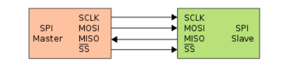
The connection between two SPI devices is typically done using 4 wires: Clock signal (SCLK), Master Out Slave In (MOSI) data line, Master In Slave Out (MISO) data line, and a chip select (SS) line activated low.
- To initiate communication, the master device must configure the clock speed to be used.
- The master sets the SS (Slave Select) line low to initiate communication.
- Next, full-duplex communication takes place: the master sends a data byte (usually 8 to 16 bits) to the slave, and the slave responds by sending a data byte back to the master.
- Additional data bytes can be sent if necessary. At the end, the master sets the SS line high, indicating to the slave that the transmission is complete.
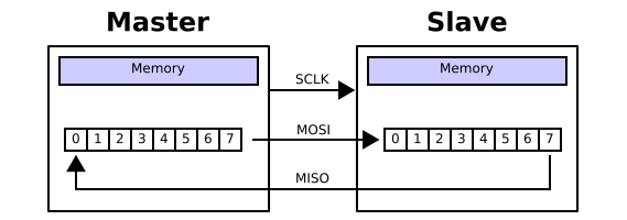
Data transmissions involve a connection of two shift registers in a ring. In this configuration, the shift registers of the master and slave are connected using two unidirectional lines between the MOSI and MISO pins. During SPI communication, data is shifted synchronously on the SCK clock edges provided by the master. The master transmits the data to be sent to the slave via the MOSI line and receives data from the slave via the MISO line. When the data frame transfer is complete (all the bits are shifted), the information between the master and slave is exchanged.
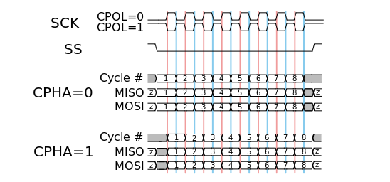
In addition to configuring the transmission frequency in the SPI protocol, the clock polarity and phase with respect to the data signals must also be set. These two options are commonly referred to as CPOL (Clock Polarity) and CPHA (Clock Phase).
- When CPOL=0, the clock is low when idle.
- When CPHA=0, data is captured on the rising edge of the clock signal (low→high).
- When CPHA=1, data is captured on the falling edge of the clock signal (high→low).
- When CPOL=1, the clock is high when idle.
- When CPHA=0, data is captured on the falling edge of the clock signal (high→low).
- When CPHA=1, data is captured on the rising edge of the clock signal (low→high).
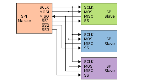
Bus Connection
The SPI communication protocol is a bus, which means that multiple devices can be connected to it. In such cases, only one device should act as the master, and the remaining devices must be set as slaves. Each slave device should have its own Slave Select (SS) line, while the Clock (SCLK), Master Output Slave Input (MOSI), and Master Input Slave Output (MISO) lines can be shared among all devices..
S32K44xx LPSPI Peripheral
The S32K144 comes with up to three SPI Hardware units each of them capable of communicate in full duplex mode using a master-slave scheme with a single master, with the possibility to handle multiple slaves via PCS pins managed by hardware or software ( manually ), plus support for DMA accesses and generates a DMA request. Main features are:
- Word size = 32 bits
- Configurable clock polarity and clock phase
- Master operation supporting up to 4 peripheral chip selects
- Slave operation
- Command/transmit FIFO of 4 words
- Receive FIFO of 4 words
- Flexible timing parameters in master mode, including SCK frequency and delays between PCS and SCK edges
- Support for full duplex transfers supporting 1-bit transmit and receive on each clock edge
- Support for half duplex transfers supporting 1-bit transmit or receive on each clock edge
- Host request can be used to control the start of a SPI bus transfer (master only)
- Receive data match logic supporting wakeup on data match
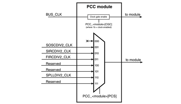
Is is important to remember the LSPI peripheral can be fed by SOSCDIV2, SIRCVDIV2, FIRCDIV2 and SPLLDIV2 clocks previously configured in the SCG peripheral or the Mcu AUTOSAR Driver
Autosar
The AUTOSAR Spi Driver is for sure the one allow us to control the LPSI peripherals found in our microcontroller as you must assume, but it is really important to understand AUTOSAR introduces new concepts we need to keep in mind in order to make a proper configuration such concepts are:
Channels
A channel defines a data channel that can be used to send data to a hardware device. Each channel has a unique identifier. It is possible to have more than one channel set up for one hardware device. For instance, the following are the channels for an EEPROM device on SPI:
• Channel for command
• Channel for address
• Channel for data
Buffers for the different channels set up can have different sizes and can be located internally in the driver or externally in your application. These are referred to as internally buffered (IB) or externally buffered (EB) channels. The IB are basically the internal FIFO buffer while the EB are an array of memory assigned by software
Jobs
A Job is composed of one or several channels with the same chip select (or the same slave). A Job is considered atomic and therefore cannot be interrupted by another Job.
A Job contains at least one channel. It can contain more than one channel. These channels are configured in a list for that Job. A Job has a priority that can be from 0 up to 3, where 0 is the lowest priority. Considered the EEPROM example a read operation or Job will consist in three channels.
A chip select is attached to a Job definition. The chip select is set at the beginning of the Job transmission and released at the end of the Job. At the end of the Job, a 'SpiJobEndNotification' is called, if configured.
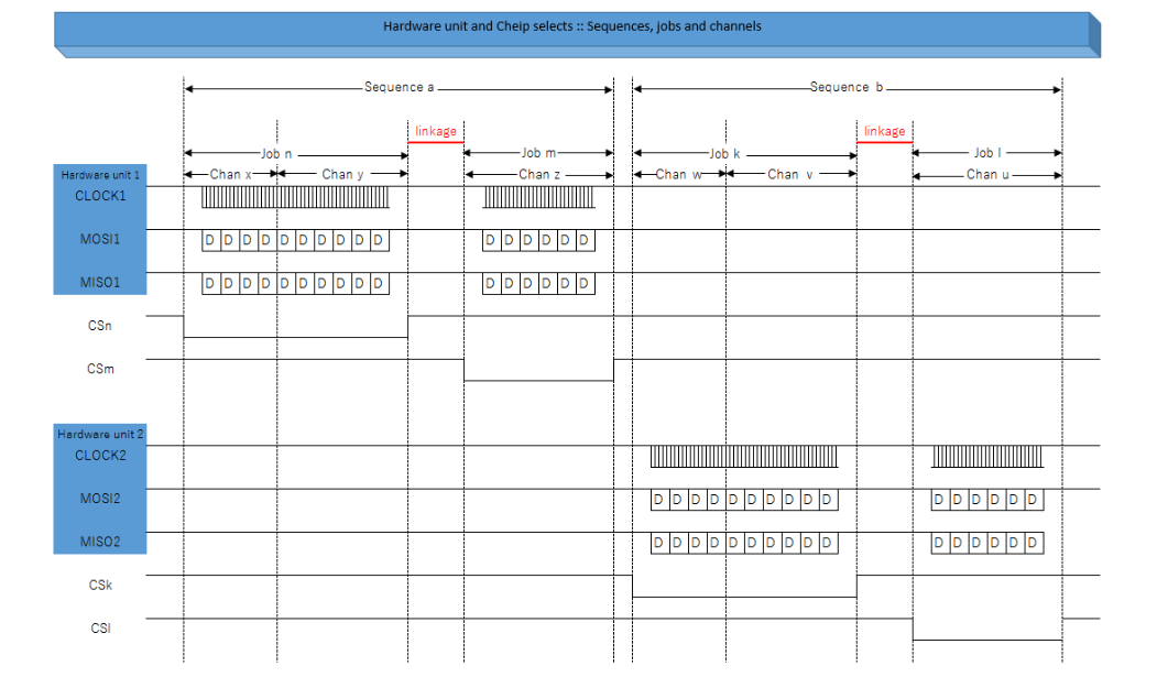
Sequences
A sequence is a number of consecutively transmitted Jobs. Jobs configured for a sequence must be in the order of priority starting with the highest priority first.
If a level 1 or level 2 driver is configured, sequences may be configured as either interruptible or non-interruptible. If a sequence is interruptible and asynchronously transmitted, Jobs from another sequence may run depending on priority. In a few less confusing words a sequence is basically a series of consecutive communications between a master and several slaves been controlled by different chip selects.
If a sequence is configured as non-interruptible, a new sequence is scheduled after the transmitting sequence, if the sequences are using the same hardware unit. If different hardware units are used, more than one sequence can be transmitted at the same time. At the end of the sequence, a 'SpiSeqEndNotification' is called, if configured
Transmission Levels
LEVEL 0, Simple Synchronous behaviour
The intention of this functionality level is to provide a Handler/Driver with a reduced set of services to handle only simple synchronous transmissions. This is often the case for ECU including simple SPI networks but also for ECU using high speed external devices. A simple synchronous transmission means that the function calling the transmission service is blocked during the ongoing transmission until the transmission is finished
LEVEL 1, Basic Asynchronous behavior
The intention of this functionality level is to provide a Handler/Driver with a reduced set of services to handle asynchronous transmissions only. This is often the case for ECU with functions related to SPI networks having different priorities but also for ECU using low speed external devices. An asynchronous transmission means that the user calling the transmission service
is not blocked when the transmission is on-going. Furthermore, the user can be notified at the end of transmission.
Usually, depending on software design, asynchronous end transmission may be detected by polling or interrupt mechanisms. This level of functionality proposes both mechanisms that are selectable during execution time.
LEVEL 2, Enhanced behaviour
The intention of this functionality level is to provide a Handler/Driver with a complete set of services to handle synchronous and asynchronous transmissions. This could be the case for ECU with a lot of functions related to SPI networks having different priorities but also for ECU using external devices with different speeds.
Usually, depending on software design, asynchronous end transmission may be detected by polling or interrupt mechanisms. This level of functionality proposes both mechanisms that are selectable during execution time.
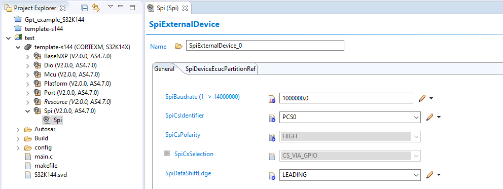
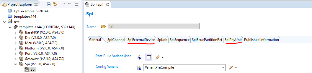
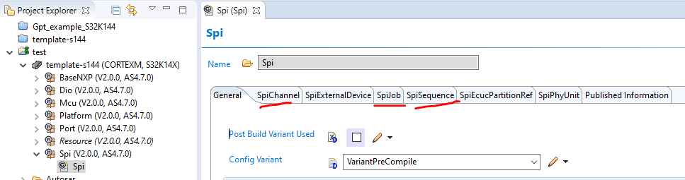
EB Tresos
To start configuring the the Spi module we need to locate the SpiExternalDevice and the SpiPhyUnit containers where we can found the typical parameter to configure our spi peripheral like the actual LPSPI to use, master or slave mode and the clock source, baud-rate, clock polarity and phase amount others. The contents of these container are really attached to the hardware characteristics of our peripheral, so it is important to read the micro reference manual to set the correct parameters.
And as your are assuming now, the SpiChannel, SpiJob and SpiSequence are the containers where we can found the parameters for the new concepts added by AUTOSAR regarding on how all the transfers shall by handled by the driver itself. The information on how to configure these container will be found in the official AUTOSAR documentation and the NXP RTD library manual for the SPI driver.
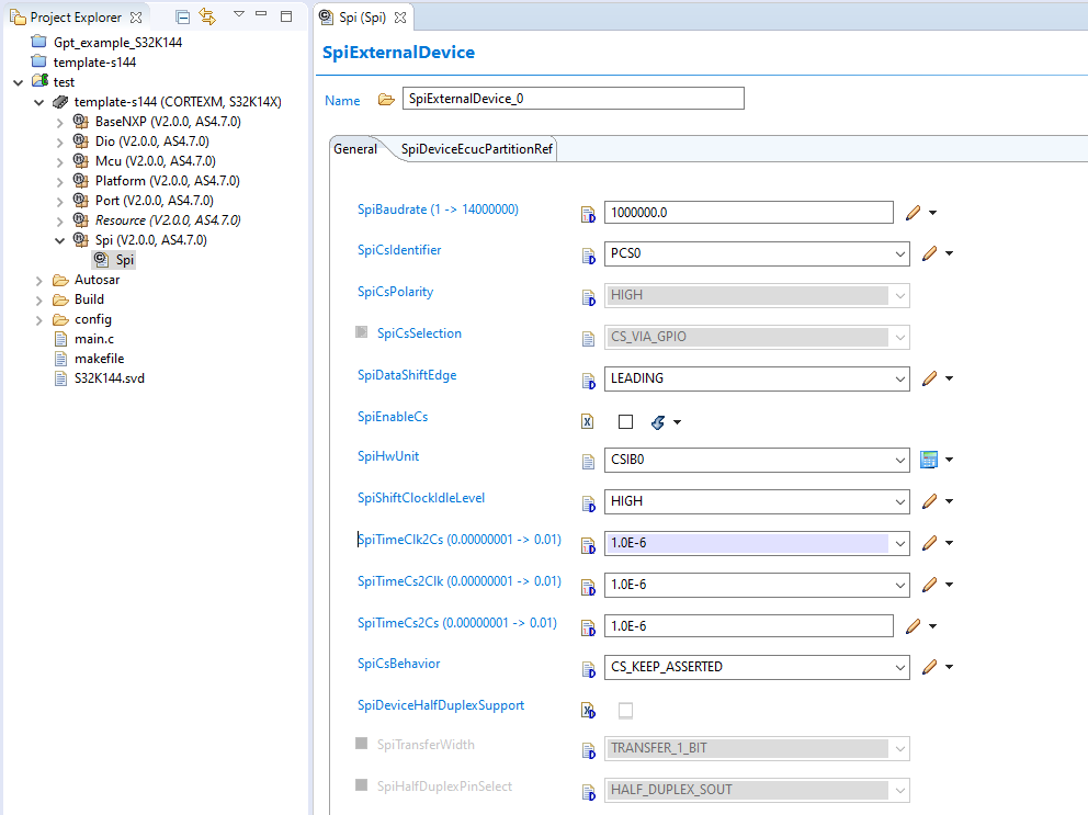
The following configuration example shows the typical hardware parameters we usually set on our SPI peripheral, so now I’m going to proceed to review each of them, because I’m a nice guy
- SpiBaudrate.- This is basically the frequency speed data is going to travel through the bus you need to keep in mid this value is used to calculated the according internal preescaler taking into account the frequency feeding the SPI module, for instance don’t try to set 10MHz while feeding the module with a frequency of 8MHz.
- SpiCsIdentifier.- Select the pin that will act as Chip Select, in master mode this only applicable if you set the SpiCsSelection to CS_VIA_PERIPHERAL_ENGINE, the values depends on how many PCS0 has the microcontroller and the LPSI module selected
- SpiCsPolarity.- the IDLE polarity of the CS pin, by rule of thump this has to b always HIGH
- SpiCsSelection.- Choose how you want to control the CS pin by hardware (automatically) or by software, using any other regular IO pin
- SpiDataShiftEdge and SpiShiftClockIdleLevel.- These parameter are basically the CPOL and CPHA ( previously explained ) configuration, their value depends on how the slave will read the data
- SpiHwUnit.- This is just the symbolic name for the SPi assigned to a Job, does not have to do with the LPSI number but rather in the logic number assigned on the SpiExternalDevice->Index
- SpiTimeClk2Cs, SpiTimeCs2Clk and SpiTimeCs2Cs.- These are time parameters for chip select delays, don't worry default values will be more than ok,
- SpiCsBehavior.- This is the behavior the chip selects should have between jobs, most of the time we will choose asserted option
Don’t worry about the other containers, you will see them in details on each of the example program we prepare for you, with our usual YAML notation
Autosar Interfaces
void Spi_JobTransferFinished (const Spi_JobConfigType ∗JobConfig, Spi_JobResultType JobResult);//This function is called after a Job has been executed.
void Spi_GetVersionInfo (Std_VersionInfoType ∗versioninfo);//This function returns the version information for the SPI driver.
void Spi_Init (const Spi_ConfigType ∗ConfigPtr);//This function initializes the SPI driver.
Std_ReturnType Spi_DeInit (void);//This function de-initializes the SPI driver.
Std_ReturnType Spi_WriteIB (Spi_ChannelType Channel, const Spi_DataBufferType ∗DataBufferPtr);//This function writes the given data into the buffer of a specific channel.
Std_ReturnType Spi_ReadIB (Spi_ChannelType Channel, Spi_DataBufferType ∗DataBufferPointer);//This function reads the data from the buffer of a channel and puts at the memory location.
Std_ReturnType Spi_AsyncTransmit (Spi_SequenceType Sequence);//This function triggers the asynchronous transmission for the given sequence.
Std_ReturnType Spi_SetupEB (Spi_ChannelType Channel, const Spi_DataBufferType ∗SrcDataBufferPtr, Spi_DataBufferType ∗DesDataBufferPtr, Spi_NumberOfDataType Length);//This function setup an external buffer to be used by a specific channel.
Spi_StatusType Spi_GetStatus (void); //This function returns the status of the SPI driver.
Spi_JobResultType Spi_GetJobResult (Spi_JobType Job);//This function is used to request the status of a specific job.
Spi_SeqResultType Spi_GetSequenceResult (Spi_SequenceType Sequence);//This function is used to request the status of a specific sequence.
Std_ReturnType Spi_SyncTransmit (Spi_SequenceType Sequence);//This function is used for synchronous transmission of a given sequence.
Spi_StatusType Spi_GetHWUnitStatus (Spi_HWUnitType HWUnit);//his function is used to request the status of a specific SPI peripheral unit.
void Spi_Cancel (Spi_SequenceType Sequence);//This function is used to request the cancelation of the given sequence.
Std_ReturnType Spi_SetAsyncMode(Spi_AsyncModeType Mode);//This function specifies the asynchronous mode for the SPI busses handled asynchronously.
Std_ReturnType Spi_SetHWUnitAsyncMode (Spi_HWUnitType HWUnit, Spi_AsyncModeType AsyncMode);//This function specifies the asynchronous mode for a given HWUnit.
void Spi_MainFunction_Handling (void);//This function shall asynchronously poll SPI interrupts and call ISR if appropriate.
Code Snippets
- SPI: Sync Transmission, 1 channel, 1 Job, 1 Sequence
- SPI: Sync Tx/Rx, 1 channel, 1 Job, 1 Sequence
- SPI: Sync Tx/Rx, 2 channels, 2 Jobs, 2 Sequences
- SPI: Sync Tx/Rx, 2 channels, 2 Jobs, 1 Sequence
- SPI: Sync Tx/Rx, Multi channels, Multi Jobs, 1 Sequence
Exercises
- Write a program to read and display with RTT the first 32 bytes of a eeprom in ASCII characters using you are free to chose the format of each number
- Modify the previous program to use one button, each time the button is pressed the content of the first 30 bytes shall be displayed
- Add a second button, every time is press a single byte should be written into the eeprom ( valid values from 0 to 29, then rollover )
- Write two functions that allow you to write and read a byte to any valid memory address in the memory, functions shall have the following prototypes
void write_byte( uint16 addr, uint8 data );
uint8_t read_byte( uint16_t addr );- Write the following functions to allow to write a given array of n number of bytes starting at any address of the eeprom
void write_data( uint16 addr, uint8 *data, uint8 size );
void read_data( uint16 addr, uint8 *data, uint8 size );