The SPI or "Serial Peripheral Interface" is a synchronous serial communication protocol, full duplex, created by Motorola. Devices are connected in Master/Slave mode, in which the master is always responsible for initiating communication.
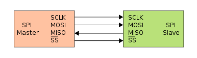
The connection between two SPI devices is typically done using 4 wires: Clock signal (SCLK), Master Out Slave In (MOSI) data line, Master In Slave Out (MISO) data line, and a chip select (SS) line activated low.
- To initiate communication, the master device must configure the clock speed to be used.
- The master sets the SS (Slave Select) line low to initiate communication.
- Next, full-duplex communication takes place: the master sends a data byte (usually 8 to 16 bits) to the slave, and the slave responds by sending a data byte back to the master.
- Additional data bytes can be sent if necessary. At the end, the master sets the SS line high, indicating to the slave that the transmission is complete.
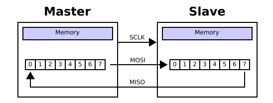
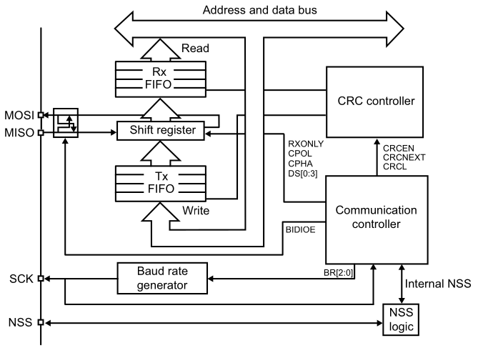
Data transmissions involve a connection of two shift registers in a ring. In this configuration, the shift registers of the master and slave are connected using two unidirectional lines between the MOSI and MISO pins. During SPI communication, data is shifted synchronously on the SCK clock edges provided by the master. The master transmits the data to be sent to the slave via the MOSI line and receives data from the slave via the MISO line. When the data frame transfer is complete (all the bits are shifted), the information between the master and slave is exchanged.
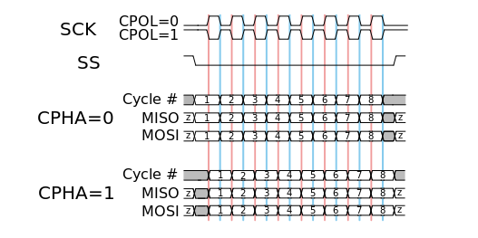
In addition to configuring the transmission frequency in the SPI protocol, the clock polarity and phase with respect to the data signals must also be set. These two options are commonly referred to as CPOL (Clock Polarity) and CPHA (Clock Phase).
- When CPOL=0, the clock is low when idle.
- When CPHA=0, data is captured on the rising edge of the clock signal (low→high).
- When CPHA=1, data is captured on the falling edge of the clock signal (high→low).
- When CPOL=1, the clock is high when idle.
- When CPHA=0, data is captured on the falling edge of the clock signal (high→low).
- When CPHA=1, data is captured on the rising edge of the clock signal (low→high).
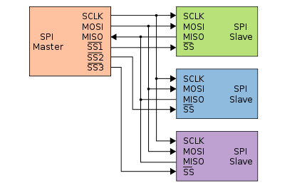
The SPI communication protocol is a bus, which means that multiple devices can be connected to it. In such cases, only one device should act as the master, and the remaining devices must be set as slaves. Each slave device should have its own Slave Select (SS) line, while the Clock (SCLK), Master Output Slave Input (MOSI), and Master Input Slave Output (MISO) lines can be shared among all devices.
STM32G0x1 SPI Peripheral
- Master or slave operation
- Full-duplex synchronous transfers on three lines
- Half-duplex synchronous transfer on two lines (with bidirectional data line)
- Simplex synchronous transfers on two lines (with unidirectional data line)
- 4 to 16-bit data size selection
- Multimaster mode capability
- 8 master mode baud rate prescalers up to fPCLK/2
- Slave mode frequency up to fPCLK/2.
- NSS management by hardware or software for both master and slave: dynamic change of master/slave operations
- Programmable clock polarity and phase
- Programmable data order with MSB-first or LSB-first shifting
- Dedicated transmission and reception flags with interrupt capability
- Hardware CRC feature for reliable communication
- Two 32-bit embedded Rx and Tx FIFOs with DMA capability
STMicroelectronics Official Video Training
STM32CubeG0 SPI HAL driver
The code to control the digital ports is located in the following libraries.
stm32g0xx_hal_spi.hstm32g0xx_hal_spi.cstm32g0xx_hal_spi_ex.hstm32g0xx_hal_spi_ex.c
In the stm32g0xx_hal_conf.h file, it is necessary to uncomment the define.
#define HAL_SPI_MODULE_ENABLED
Functions
/* Transfer function in blocking mode */
HAL_StatusTypeDef HAL_SPI_Transmit(SPI_HandleTypeDef *hspi, uint8_t *pData, uint16_t Size, uint32_t Timeout);
HAL_StatusTypeDef HAL_SPI_Receive(SPI_HandleTypeDef *hspi, uint8_t *pData, uint16_t Size, uint32_t Timeout);
HAL_StatusTypeDef HAL_SPI_TransmitReceive(SPI_HandleTypeDef *hspi, uint8_t *pTxData, uint8_t *pRxData, uint16_t Size, uint32_t Timeout);
/* Transfer function in interrupt mode */
HAL_StatusTypeDef HAL_SPI_Transmit_IT(SPI_HandleTypeDef *hspi, uint8_t *pData, uint16_t Size);
HAL_StatusTypeDef HAL_SPI_Receive_IT(SPI_HandleTypeDef *hspi, uint8_t *pData, uint16_t Size);
HAL_StatusTypeDef HAL_SPI_TransmitReceive_IT(SPI_HandleTypeDef *hspi, uint8_t *pTxData, uint8_t *pRxData, uint16_t Size);
/* Transfer function in DMA mode */
HAL_StatusTypeDef HAL_SPI_Transmit_DMA(SPI_HandleTypeDef *hspi, uint8_t *pData, uint16_t Size);
HAL_StatusTypeDef HAL_SPI_Receive_DMA(SPI_HandleTypeDef *hspi, uint8_t *pData, uint16_t Size);
HAL_StatusTypeDef HAL_SPI_TransmitReceive_DMA(SPI_HandleTypeDef *hspi, uint8_t *pTxData, uint8_t *pRxData, uint16_t Size);
HAL_StatusTypeDef HAL_SPI_DMAPause(SPI_HandleTypeDef *hspi);
HAL_StatusTypeDef HAL_SPI_DMAResume(SPI_HandleTypeDef *hspi);
HAL_StatusTypeDef HAL_SPI_DMAStop(SPI_HandleTypeDef *hspi);
/* Transfer Abort functions */
HAL_StatusTypeDef HAL_SPI_Abort(SPI_HandleTypeDef *hspi);
HAL_StatusTypeDef HAL_SPI_Abort_IT(SPI_HandleTypeDef *hspi);
/* Callback top use within an ISR */
void HAL_SPI_IRQHandler(SPI_HandleTypeDef *hspi);
void HAL_SPI_TxCpltCallback(SPI_HandleTypeDef *hspi);
void HAL_SPI_RxCpltCallback(SPI_HandleTypeDef *hspi);
void HAL_SPI_TxRxCpltCallback(SPI_HandleTypeDef *hspi);
void HAL_SPI_TxHalfCpltCallback(SPI_HandleTypeDef *hspi);
void HAL_SPI_RxHalfCpltCallback(SPI_HandleTypeDef *hspi);
void HAL_SPI_TxRxHalfCpltCallback(SPI_HandleTypeDef *hspi);
void HAL_SPI_ErrorCallback(SPI_HandleTypeDef *hspi);
void HAL_SPI_AbortCpltCallback(SPI_HandleTypeDef *hspi);
Configuration Structure
typedef struct
{
    uint32_t Mode;                /*!< Specifies the SPI operating mode */
    uint32_t Direction;           /*!< Specifies the SPI bidirectional mode state. */
    uint32_t DataSize;            /*!< Specifies the SPI data size */
    uint32_t CLKPolarity;         /*!< Specifies the serial clock steady state */
    uint32_t CLKPhase;            /*!< Specifies the clock active edge for the bit capture */
    uint32_t NSS;                 /*!< Specifies whether the NSS signal is managed by hardware (NSS pin) or by software using the SSI bit. */
    uint32_t BaudRatePrescaler;   /*!< Specifies the Baud Rate prescaler value which will be used to configure the transmit and receive SCK clock. */
    uint32_t FirstBit;            /*!< Specifies whether data transfers start from MSB or LSB bit. */
    uint32_t TIMode;              /*!< Specifies if the TI mode is enabled or not. */
    uint32_t CRCCalculation;      /*!< Specifies if the CRC calculation is enabled or not. */
    uint32_t CRCPolynomial;       /*!< Specifies the polynomial used for the CRC calculation. This parameter must be an odd number between Min_Data = 1 and Max_Data = 65535 */
    uint32_t CRCLength;           /*!< Specifies the CRC Length used for the CRC calculation. CRC Length is only used with Data8 and Data16, not other data size */
    uint32_t NSSPMode;            /*!< Specifies whether the NSSP signal is enabled or not  */
} SPI_InitTypeDef;
Code Snippets
- SPI: Sending a message through SPI
- SPI: Receiving a message through SPI
- SPI: Send and Receive a message
- SPI: Send a message with Interrupts
- SPI: Receive a message with Interrupts
- SPI: Sending message via SPI with DMA
- SPI: Receiving message via SPI with DMA
Exercises:
- Write a program to read and display the first 32 bytes of a eeprom in ASCII characters using the serial port, you are free to chose the format of each number
- Modify the previous program to use one button, each time the button is pressed the content of the first 30 bytes shall be displayed
- Add a second button, every time is press a single byte should be written into the eeprom ( valid values from 0 to 29, then rollover )
- Alter the program to read data from the eeprom using the DMA
- Fill the eeprom with the string "hello world\r\n"
- Write two functions that allow you to write and read a byte to any valid memory address in the memory, functions shall have the following prototype
void write_byte( uint16_t addr, uint8_t data );,uint8_t read_byte( uint16_t addr ); - Write the following functions to allow to write a given array of n number of bytes starting at any address of the eeprom.
void write_data( uint16_t addr, uint8_t *data, uint8_t size );andvoid read_data( uint16_t addr, uint8_t *data, uint8_t size );