An Analog-to-Digital Converter (ADC) is an electronic device capable of converting an analog voltage signal into a digital signal with a binary value. Computers or any control system based on a microprocessor cannot interpret analog signals as they only use digital signals. It is necessary to translate or transform them into binary signals.
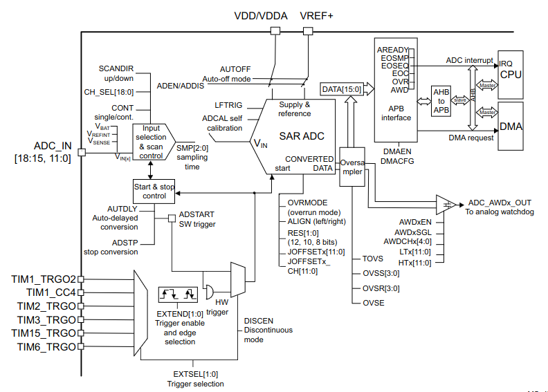
This Successive Approximation Register (SAR) ADC module has a maximum resolution of 12 bits and 19 multiplexed channels, with 16 of them being external and 3 internal, including a temperature sensor and another for measuring the VBAT voltage.
I could provide a further explanation of how a SAR-type ADC works, but it is already well explained on this page. https://circuitdigest.com/article/how-does-successive-approximation-sar-adc-work-and-where-is-it-best-used
STM32G0 ADC main features
- High performance
- 12-bit, 10-bit, 8-bit or 6-bit configurable resolution
- ADC conversion time: 0.4 μs for 12-bit resolution (2.5Msps), faster conversion times can be obtained by lowering resolution.
- Self-calibration
- Programmable sampling time
- Data alignment with built-in data coherency
- DMA support
- Analog input channels
- 16 external analog inputs
- 1 channel for internal temperature sensor (VSENSE )
- 1 channel for internal reference voltage (V REFINT)
- 1 channel for monitoring external VBAT power supply pin
- Start-of-conversion can be initiated:
- By software
- By hardware triggers with configurable polarity (timer events or GPIO input events)
- Conversion modes
- Can convert a single channel or can scan a sequence of channels.
- Single mode converts selected inputs once per trigger
- Continuous mode converts selected inputs continuously
- Discontinuous mode
- Interrupt generation at the end of sampling, end of conversion, end of sequence conversion, and in case of analog watchdog or overrun events
- Analog watchdog
- Oversampler
- 16-bit data register
- Oversampling ratio adjustable from 2 to 256x
- Programmable data shift up to 8-bits
- ADC supply requirements: 1.62 to 3.6 V
- ADC input range: V SSA ≤ V IN ≤ V REF+
The ADC needs some time in order to sample a signal and then perform a convertion into a digital value, and this time will be affected by the clock speed, a fixed convertion value and the resolution set ( 6, 8, 10 or 12 bits), here is an example for and 1MHz clock and 8 bit resolution
Convertion timing is given by the following formula:
      Tcon = ( Tsampling + Tconv ) / ADC clock
      Tcon = ( 1.5 + 8.5 ) / 8MHz = 1.us*/
From the point of view of the HAL library, conversion time is given by the values set in the following config structure elements
Tcon = ( AdcHandler.Init.SamplingTimeCommon1 + AdcHandler.Init.Resolution ) / (Fadc / AdcHandler.Init.ClockPrescaler)STMicroelectronics Official Video Training
STM32CubeG0 ADC HAL driver
The code to control the digital ports is located in the following libraries.
stm32g0xx_hal_adc.hstm32g0xx_hal_adc.cstm32g0xx_hal_adc_ex.hstm32g0xx_hal_adc_ex.c
In the stm32g0xx_hal_conf.h file, it is necessary to uncomment the define.
#define HAL_ADC_MODULE_ENABLED
Functions
HAL_StatusTypeDef       HAL_ADC_Init(ADC_HandleTypeDef *hadc);
HAL_StatusTypeDef       HAL_ADC_DeInit(ADC_HandleTypeDef *hadc);
void                    HAL_ADC_MspInit(ADC_HandleTypeDef *hadc);
void                    HAL_ADC_MspDeInit(ADC_HandleTypeDef *hadc);
/* Blocking mode: Polling */
HAL_StatusTypeDef       HAL_ADC_Start(ADC_HandleTypeDef *hadc);
HAL_StatusTypeDef       HAL_ADC_Stop(ADC_HandleTypeDef *hadc);
HAL_StatusTypeDef       HAL_ADC_PollForConversion(ADC_HandleTypeDef *hadc, uint32_t Timeout);
HAL_StatusTypeDef       HAL_ADC_PollForEvent(ADC_HandleTypeDef *hadc, uint32_t EventType, uint32_t Timeout);
/* Non-blocking mode: Interruption */
HAL_StatusTypeDef       HAL_ADC_Start_IT(ADC_HandleTypeDef *hadc);
HAL_StatusTypeDef       HAL_ADC_Stop_IT(ADC_HandleTypeDef *hadc);
/* Non-blocking mode: DMA */
HAL_StatusTypeDef       HAL_ADC_Start_DMA(ADC_HandleTypeDef *hadc, uint32_t *pData, uint32_t Length);
HAL_StatusTypeDef       HAL_ADC_Stop_DMA(ADC_HandleTypeDef *hadc);
/* ADC retrieve conversion value intended to be used with polling or interruption */
uint32_t                HAL_ADC_GetValue(ADC_HandleTypeDef *hadc);
/* ADC IRQHandler and Callbacks used in non-blocking modes (Interruption and DMA) */
void                    HAL_ADC_IRQHandler(ADC_HandleTypeDef *hadc);
void                    HAL_ADC_ConvCpltCallback(ADC_HandleTypeDef *hadc);
void                    HAL_ADC_ConvHalfCpltCallback(ADC_HandleTypeDef *hadc);
void                    HAL_ADC_LevelOutOfWindowCallback(ADC_HandleTypeDef *hadc);
void                    HAL_ADC_ErrorCallback(ADC_HandleTypeDef *hadc);
/* Peripheral Control functions*/
HAL_StatusTypeDef       HAL_ADC_ConfigChannel(ADC_HandleTypeDef *hadc, ADC_ChannelConfTypeDef *pConfig);
HAL_StatusTypeDef       HAL_ADC_AnalogWDGConfig(ADC_HandleTypeDef *hadc, ADC_AnalogWDGConfTypeDef *pAnalogWDGConfig);
/* Peripheral State functions */
uint32_t                HAL_ADC_GetState(ADC_HandleTypeDef *hadc);
uint32_t                HAL_ADC_GetError(ADC_HandleTypeDef *hadc);
Initialization Structure
typedef struct
{
  uint32_t ClockPrescaler;        /*!< Select ADC clock source (synhronous clock derived from APB clock or asynchronou */
  uint32_t Resolution;            /*!< Configure the ADC resolution.*/
  uint32_t DataAlign;             /*!< Specify ADC data alignment in conversion data register (right or left)*/
  uint32_t ScanConvMode;          /*!< Configure the sequencer of ADC group regular */
  uint32_t EOCSelection;          /*!< Specify which EOC (End Of Conversion) end of unitary conversion or end of sequence conversions */
  FunctionalState LowPowerAutoWait;       /*!< Select the dynamic low power Auto Delay*/
  FunctionalState LowPowerAutoPowerOff;   /*!< Select the auto-off mode */
  FunctionalState ContinuousConvMode;     /*!< Specify whether the conversion is performed in single mode (one conversion)
                                              or continuous mode for ADC group regular*/
  uint32_t NbrOfConversion;               /*!< Specify the number of ranks that will be converted within the regular group sequencer.*/
  FunctionalState DiscontinuousConvMode;  /*!< Specify whether the conversions sequence of ADC group regular is performed */
  uint32_t ExternalTrigConv;              /*!< Select the external event source used to trigger ADC group regular conversion start.*/
  uint32_t ExternalTrigConvEdge;          /*!< Select the external event edge used to trigger ADC group regular conversion start */
  FunctionalState DMAContinuousRequests;  /*!< Specify whether the DMA requests are performed in one shot mode or in continuous mode */
  uint32_t Overrun;                       /*!< Select the behavior in case of overrun: data overwritten or preserved (default).*/
  uint32_t SamplingTimeCommon1;           /*!< Set sampling time common to a group of channels.*/
  uint32_t SamplingTimeCommon2;           /*!< Set sampling time common to a group of channels, */
  FunctionalState OversamplingMode;       /*!< Specify whether the oversampling feature is enabled or disabled.*/
  ADC_OversamplingTypeDef Oversampling;   /*!< Specify the Oversampling parameters.*/
  uint32_t TriggerFrequencyMode;          /*!< Set ADC trigger frequency mode. */

} ADC_InitTypeDef;
Code Snippets
- ADC: Single channel, Single conversion, Polling
- ADC: Two channels, Single conversion, Polling
- ADC: Two channels, Single conversion, Polling, Custom sequence
- ADC: Single channel, Single conversion, Interrupt
- ADC: Two channels, Single conversion, Interrupts
- ADC: Single channel, Single conversion, Interrupts, Hardware trigger
- ADC: Two channels, Continuous conversion, DMA
Exercises
- Vary the rotation speed of an LED connected to the eight LEDs using one of the potentiometers on the board.
- Display the values of the two potentiometers in Ohms and Volts (since printf does not support floating-point numbers, adapt the display to simulate the floating-point).
- Modify the second sample code to have a 12-bit resolution for reading the potentiometers, and take three readings to display their average value.
- Control the blinking speed of two LEDs from 100ms to 1000ms in intervals of 50ms. Each LED will be controlled separately using its respective potentiometer.
- In the previous program, add a control so that the speed variation only takes effect when the button is held down. Add a control button for each potentiometer.
- The MCU has an internal temperature sensor connected to an ADC channel. Display the temperature using semihosting (NOTE: to vary the temperature, rub your fingers and touch the microcontroller with one of them, do not use external heat as it may damage the microcontroller).
- Display the value of the first potentiometer in Ohms, the second one in Volts, and also the temperature of the microcontroller. This time, take continuous readings every two seconds using a TIM timer. The timer should trigger the ADC readings automatically without any code intervention.
- Modify the third example program to work with DMA