Most of the digital systems needs its own clock signal in order to work , amount other things it give us the speed in which most of the operation are going to be carried out. Every modern microcontroller has different clock sources ( internal or externals ) that can or not be multiplied in order to produce high frequencies, also more than one source can be use to feed several peripherals in order to adjust the needs of our programs, not every peripheral needs the maximum mcu frequency, actually several of them work really well with low frequencies.
The device provides the following clock sources producing primary clocks. Each oscillator can be switched on or off independently when it is not used, to optimize
power consumption.
- HSI16 RC ( internal ) - a high-speed fully-integrated RC oscillator producing HSI16 clock (about 16 MHz)
- HSI48 RC ( internal ) - a high-speed fully-integrated RC oscillator producing HSI48 clock for USB (about 48 MHz)
- HSE OSC ( external ) - a high-speed oscillator with external crystal/ceramic resonator or external clock source, producing HSE clock (4 to 48 MHz)
- LSI RC ( internal low power ) - a low-speed fully-integrated RC oscillator producing LSI clock (about 32 kHz)
- LSE OSC ( external low power ) - a low-speed oscillator with external crystal/ceramic resonator or external clock source, producing LSE clock (accurate 32.768 kHz or external clock up to 1 MHz)
- I2S_CKIN ( external ) - pin for direct clock input for I2S1 peripheral
The device produces secondary clocks by dividing or/and multiplying the primary clocks:
- HSISYS - a clock derived from HSI16 through division by a factor programmable from 1 to 128
- PLLPCLK, PLLQCLK and PLLRCLK - clocks output from the PLL block
- SYSCLK - a clock obtained through selecting one of LSE, LSI, HSE, PLLRCLK, and HSISYS clocks
- HCLK - a clock derived from SYSCLK through division by a factor programmable from 1 to 512
- HCLK8 - a clock derived from HCLK through division by eight
- PCLK - a clock derived from HCLK through division by a factor programmable from 1 to 16
- TIMPCLK - a clock derived from PCLK, running at PCLK frequency if the APB prescaler division factor is set to 1, or at twice the PCLK frequency otherwise
- LPTIMx_IN - clock from LPTIMx_INx pins, selectable for the LPTIM peripheral
- More secondary clocks are generated by fixed division of HSE, HSI16 and HCLK clocks. The HSISYS is used as system clock source after startup from reset, with the division by 1
(producing HSI16 frequency). The HCLK clock and PCLK clock are used for clocking the AHB and the APB domains, respectively. Their maximum allowed frequency is 64 MHz
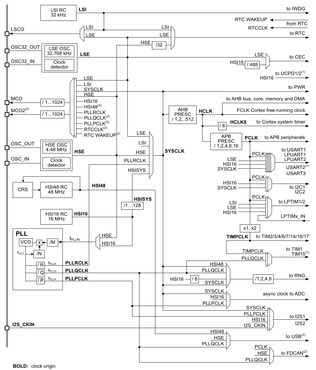
The external oscillator (HSE) can generate its frequency from a crystal or an oscillator, while the internal oscillator (HSI16) takes the frequency from a 16MHz internal RC oscillator. Both clock sources can feed into the frequency multiplier (PLL) to provide the necessary frequency to the main oscillator. On the other hand, the other internal oscillator (HSI48) is only used to feed the USB and RNG. The frequency multiplier (PLL) has two clock inputs (HSE and HSI) and three outputs. The primary output is PLLRCLK, which becomes SYSCLK and feeds the CPU and AHB and APB buses.
In addition to the main clock, the STM32G0 microcontrollers feature a secondary low-frequency clock. This clock can be sourced either externally or internally.Two pins on the microcontroller (MCO1 and MCO2) can be used to output different frequencies from the microcontroller: LSI, LSE, SYSCLK, HSI16, HSI48, HSE, PLLPCLK, PLLQCLK, PLLRCLK, RTCCLK, and RTC WAKEUP. Both outputs can be divided using the RCC_CFGR register. There is a third pin (LSCO) that allows you to output frequencies exclusively from the LSI and LSE oscillators.
PLL Configuration
In the PLLCFGR register, you configure the multipliers and dividers that allow the PLL to generate frequencies. The PLL generates the output frequencies (fPLLP, fPLLQ, fPLLR) based on the input frequency (fPLLIN) and VCO frequency (fVCO), as well as the division factors P, Q, and R.
- fVCO = fPLLIN x (N / M)
- fPLLP = fVCO / P
- fPLLQ = fVCO / Q
- fPLLR = fVCO / R
STMicroelectronics Official Video Training
STM32CubeG0 RCC HAL driver
The code to control the Reset Clock Control is located in the following libraries. make sure the source file is added into the makefile
stm32g0xx_hal_rcc.hstm32g0xx_hal_rcc.cstm32g0xx_hal_rcc_ex.hstm32g0xx_hal_rcc_ex.cstm32g0xx_hal_pwr.hstm32g0xx_hal_pwr.c
In the stm32g0xx_hal_conf.h file, it is necessary to uncomment the define.
#define HAL_RCC_MODULE_ENABLED
#define HAL_PWR_MODULE_ENABLED
Functions
HAL_StatusTypeDef HAL_RCC_DeInit(void);
HAL_StatusTypeDef HAL_RCC_OscConfig(RCC_OscInitTypeDef *RCC_OscInitStruct);
HAL_StatusTypeDef HAL_RCC_ClockConfig(RCC_ClkInitTypeDef *RCC_ClkInitStruct, uint32_t FLatency);
void              HAL_RCC_MCOConfig(uint32_t RCC_MCOx, uint32_t RCC_MCOSource, uint32_t RCC_MCODiv);
void              HAL_RCC_EnableCSS(void);
void              HAL_RCC_EnableLSECSS(void);
void              HAL_RCC_DisableLSECSS(void);
uint32_t          HAL_RCC_GetSysClockFreq(void);
uint32_t          HAL_RCC_GetHCLKFreq(void);
uint32_t          HAL_RCC_GetPCLK1Freq(void);
void              HAL_RCC_GetOscConfig(RCC_OscInitTypeDef *RCC_OscInitStruct);
void              HAL_RCC_GetClockConfig(RCC_ClkInitTypeDef *RCC_ClkInitStruct, uint32_t *pFLatency);
uint32_t          HAL_RCC_GetResetSource(void);
void              HAL_RCC_NMI_IRQHandler(void);
void              HAL_RCC_CSSCallback(void);
void              HAL_RCC_LSECSSCallback(void);
Extra Functions
HAL_StatusTypeDef HAL_RCCEx_PeriphCLKConfig(RCC_PeriphCLKInitTypeDef  *PeriphClkInit);
void              HAL_RCCEx_GetPeriphCLKConfig(RCC_PeriphCLKInitTypeDef  *PeriphClkInit);
uint32_t          HAL_RCCEx_GetPeriphCLKFreq(uint32_t PeriphClk);
void              HAL_RCCEx_EnableLSCO(uint32_t LSCOSource);
void              HAL_RCCEx_DisableLSCO(void);
Initialization Structure
typedef struct
{
    uint32_t OscillatorType;       /*!< The oscillators to be configured.*/
    uint32_t HSEState;             /*!< The new state of the HSE.*/
    uint32_t LSEState;             /*!< The new state of the LSE.*/
    uint32_t HSIState;             /*!< The new state of the HSI.*/
    uint32_t HSIDiv;               /*!< The division factor of the HSI16.*/
    uint32_t HSICalibrationValue;  /*!< The calibration trimming value (default is RCC_HSICALIBRATION_DEFAULT).*/
    uint32_t LSIState;             /*!< The new state of the LSI.*/
    uint32_t HSI48State;           /*!< The new state of the HSI48 (only applicable to STM32G0C1xx/STM32G0B1xx/STM32G0B0xx devices).*/
    RCC_PLLInitTypeDef PLL;        /*!< Main PLL structure parameters*/
} RCC_OscInitTypeDef;
PLL config structure
typedef struct
{
    uint32_t PLLState;   /* The new state of the PLL */
    uint32_t PLLSource;  /* RCC_PLLSource: PLL entry clock source */
    uint32_t PLLM;       /* PLLM: Division factor for PLL VCO input clock */
    uint32_t PLLN;       /* PLLN: Multiplication factor for PLL VCO output clock.*/
    uint32_t PLLP;       /* PLLP: PLL Division factor.User have to set the PLLQ parameter correctly to not exceed max frequency 64MHZ */
    uint32_t PLLQ;       /* PLLQ: PLL Division factor. User have to set the PLLQ parameter correctly to not exceed max frequency 64MHZ.*/
    uint32_t PLLR;       /* PLLR: PLL Division for the main system clock. User have to set the PLLR parameter correctly to not exceed max frequency 64MHZ.*/
} RCC_PLLInitTypeDef;
Busses configuration structure
typedef struct
{
    uint32_t ClockType;             /* The clock to be configured */
    uint32_t SYSCLKSource;          /* The clock source used as system clock (SYSCLK) */
    uint32_t AHBCLKDivider;         /* The AHB clock (HCLK) divider. This clock is derived from the system clock (SYSCLK) */
    uint32_t APB1CLKDivider;        /* The APB1 clock (PCLK1) divider. This clock is derived from the AHB clock (HCLK) */
} RCC_ClkInitTypeDef;
Code Snippets
Exercises
- Set the clock frequency up to 64 MHz and APB bus to 32MHz, then configure the serial port to 115200 bauds and transmit one message every one second, using a TIM1 timer
- Modify the previous program to feed the UART with the HSI16 clock directly and the TIM1 timer with the PLLQCLK clock at 8MHz
- From the previous program output the PLLQCLK in MCO pin and SYSCLK in MCO2 pin