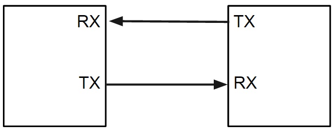
A serial port, also known as a serial interface, is a digital data communication interface where information is transmitted bit by bit, sending one bit at a time. Serial ports are perhaps, alongside timers, two of the most common and oldest peripherals that can be found in a microcontroller.
While other interfaces like Ethernet and USB transmit data as a serial stream, the term "serial port" typically refers to hardware that follows the RS-232 standard. Currently, the USB interface has replaced the serial port due to its faster speed, rendering the serial port obsolete. However, serial ports are still found in industrial automation systems and some consumer products.
Serial ports communicate asynchronously, which means that between two devices, there isn't a shared clock signal.
Configuration Parameters
Baudrate
One of the parameters that can be set in serial communication is the speed at which data travels. This is measured in bits per second or baud rate and standard speeds are established: 4300, 9600, 19200, 57600 or 115200
Data
Another parameter that we can configure is the number of bits that make up a single data unit.
- 5 bits. BaudCode
- 6 bits.
- 7 bits. True ASCII
- 8 bits. Byte data size
- 9 bits. RS485 protocol
Parity
Parity is an error detection method that involves sending an additional bit with each data unit to indicate whether the number of "1" bits is even or odd. There are two types of parity: even parity and odd parity.
bits data | “1“ number | Parity Even | Parity Odd |
|---|---|---|---|
0000000 | 0 | 00000000 | 00000001 |
1010001 | 3 | 10100011 | 10100010 |
1011001 | 4 | 10110010 | 10110011 |
Bits de stop
Stop bits are sent at the end of each character and are used to detect the end of a character and give the receiving equipment a chance to resynchronize. They can be configured as follows:
- 1
- 1.5
- 2
Flow control
The serial port can use additional signals to pause and resume communication between two devices. This is used when either of the systems needs to process information while it is being sent. Flow control can be:
- Por Hardware CTS/RTS
- Por software XON/XOFF
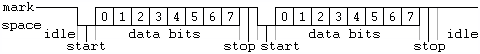
Serial Frame
The structure of a serial data transmission frame consists of a start bit indicating the beginning of transmission, followed by the data (8 bits), and ending with one or two stop bits. That makes that for every bytes seeded in reality are 10 bits been send. This is important at the moment of calculate how much time one single data takes to to be transmitted o received.
Calculate how much time takes to transmit one single byte with the following configuration:
- 57600
- 1 stop bit
- 8 bits
- No parity neither flow control
STMicroelectronics Official Video Training
STM32CubeG0 UART HAL driver
The code to control the digital ports is located in the following libraries. make sure the source file is added into the makefile
stm32g0xx_hal_uart.hstm32g0xx_hal_uart.cstm32g0xx_hal_uart_ex.hstm32g0xx_hal_uart_ex.c
In the stm32g0xx_hal_conf.h file, it is necessary to uncomment the define.
#define HAL_UART_MODULE_ENABLED
Functions
HAL_StatusTypeDef HAL_UART_Transmit(UART_HandleTypeDef *huart, const uint8_t *pData, uint16_t Size, uint32_t Timeout);
HAL_StatusTypeDef HAL_UART_Receive(UART_HandleTypeDef *huart, uint8_t *pData, uint16_t Size, uint32_t Timeout);
HAL_StatusTypeDef HAL_UART_Transmit_IT(UART_HandleTypeDef *huart, const uint8_t *pData, uint16_t Size);
HAL_StatusTypeDef HAL_UART_Receive_IT(UART_HandleTypeDef *huart, uint8_t *pData, uint16_t Size);
HAL_StatusTypeDef HAL_UART_Transmit_DMA(UART_HandleTypeDef *huart, const uint8_t *pData, uint16_t Size);
HAL_StatusTypeDef HAL_UART_Receive_DMA(UART_HandleTypeDef *huart, uint8_t *pData, uint16_t Size);
HAL_StatusTypeDef HAL_UART_DMAPause(UART_HandleTypeDef *huart);
HAL_StatusTypeDef HAL_UART_DMAResume(UART_HandleTypeDef *huart);
HAL_StatusTypeDef HAL_UART_DMAStop(UART_HandleTypeDef *huart);

void HAL_UART_IRQHandler(UART_HandleTypeDef *huart);
void HAL_UART_TxHalfCpltCallback(UART_HandleTypeDef *huart);
void HAL_UART_TxCpltCallback(UART_HandleTypeDef *huart);
void HAL_UART_RxHalfCpltCallback(UART_HandleTypeDef *huart);
void HAL_UART_RxCpltCallback(UART_HandleTypeDef *huart);
void HAL_UART_ErrorCallback(UART_HandleTypeDef *huart);
void HAL_UART_AbortCpltCallback(UART_HandleTypeDef *huart);
void HAL_UART_AbortTransmitCpltCallback(UART_HandleTypeDef *huart);
void HAL_UART_AbortReceiveCpltCallback(UART_HandleTypeDef *huart);
void HAL_UARTEx_RxEventCallback(UART_HandleTypeDef *huart, uint16_t Size);

HAL_UART_StateTypeDef HAL_UART_GetState(const UART_HandleTypeDef *huart);
uint32_t              HAL_UART_GetError(const UART_HandleTypeDef *huart);
Configuration structure
typedef struct
{
    uint32_t BaudRate;                /*!< This member configures the UART communication baud rate */
    uint32_t WordLength;              /*!< Specifies the number of data bits transmitted or received in a frame */
    uint32_t StopBits;                /*!< Specifies the number of stop bits transmitted */
    uint32_t Parity;                  /*!< Specifies the parity mode */
    uint32_t Mode;                    /*!< Specifies whether the Receive or Transmit mode is enabled or disabled*/
    uint32_t HwFlowCtl;               /*!< Specifies whether the hardware flow control mode is enabledor disabled */
    uint32_t OverSampling;            /*!< Specifies whether the Over sampling 8 is enabled or disabled, to achieve higher speed (up to f_PCLK/8)*/
    uint32_t OneBitSampling;          /*!< Specifies whether a single sample or three samples' majority vote is selected.
                                         Selecting the single sample method increases the receiver tolerance to clock deviations */
    uint32_t ClockPrescaler;          /*!< Specifies the prescaler value used to divide the UART clock source.*/
} UART_InitTypeDef;
Code Snippets
- UART: Single Msg polling transmission
- UART: Single Transmission with interrupts
- UART: Reception of messages with polling
- UART: Reception using interrupts
Exercises
You can use the function sprintf or create your own version of itoa and atoi
- Create a program that displays the count of a variable in the terminal every second. The count will be from 0 to 9 and then start again.
- Modify the previous program for a count from 0 to 500.
- Write a program that rotates an LED from left to right every 2 seconds and indicates which LED is on through the serial port. At the same time, make another LED blink every 300ms.
- Display the value of a variable in binary through the serial port.
- Display the value of the global variable SystemCoreClock through the serial port.
- Write a program that determines whether the received character is a number or a letter. Use LEDs to indicate this.
- Modify the previous program to respond through the serial port whether it was a letter or a number.
- Write a program that receives a three-digit number through the serial port, and that number indicates the time in milliseconds that an LED should be blinking. NOTE: The program should discern whether it is a number equal to or less than three digits or if it is simply not a valid number