Measuring time is one of the basic needs within any program, and programs for microcontrollers are no exception. We can generate time intervals by counting instructions of the CPU itself, but this method, although simple, is often inefficient and imprecise.
A peripheral used for measuring time is the Timer, a peripheral that is very common and essential in any microcontroller. Timers "count" clock pulses, which usually come from the same source that feeds the system's CPU frequency. The Timer is typically a simple 8, 16, or 32-bit register that increases its value with each new pulse generated. The pulses that reach the Timer are usually divided or pre-scaled to slow down its counting and obtain longer time intervals. Once its count reaches a maximum value, an overflow event occurs (a flag and/or interruption is activated).
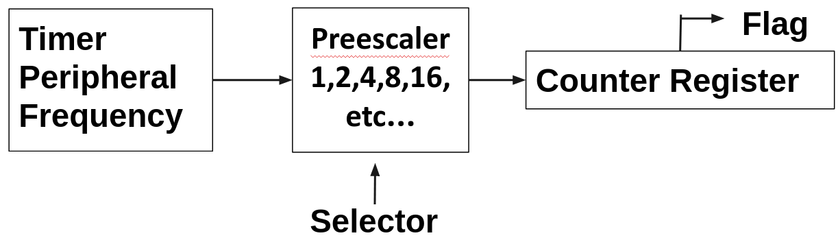
The following diagram is a very basic representation of a typical Timer within a microcontroller, consisting of a counter register, prescaler, and clock source. The clock source provides the input pulses to the Timer, which are then divided or pre-scaled by the prescaler. The resulting pulses are used to increment the value in the counter register. As the counter value increases, it represents the elapsed time. When the counter reaches its maximum value, an overflow event may occur, triggering a flag or interrupt. This basic structure allows the Timer to measure time intervals by counting pulses and provide various timing functionalities in microcontroller applications.
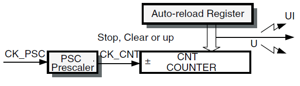
TIM timers have a special register called the "Auto-reload Register" that allows setting a maximum count value. When the counter reaches the value in this register, an event can occur, such as resetting the timer to zero, stopping the timer, or triggering an interrupt.
The following figures show some examples of the counter behavior for different clock frequencies when the Auto-reload register = 0x36.
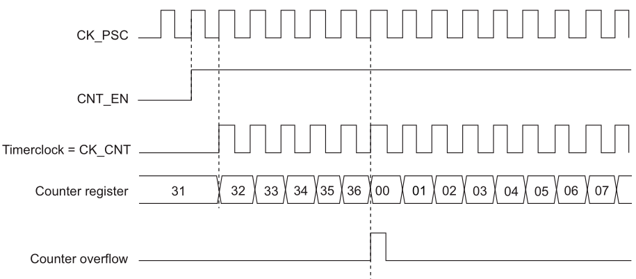
So, how can we calculate time?. Let's get the equivalent time for a count of 36 with following fictional data
- Frequency feeding the timer = 8MHz
- Preescaler of value = 10
Frequency overflow = Ftimer / Prescaler / Count Register
Frequency overflow = 8MHz / 10 / 36
Frequency overflow = 22.222KHz
Timeout = 1 / Frequency Overflow
Timeout = 45us
The timers available in the STM32G0 microcontroller family are identified with the prefix TIM and are divided into four groups:
- Basic Timers (TIM6 and TIM7). These are simple timers that provide basic timing functionalities.
- General Purpose Timers 16/32 bits (TIM2 - TIM4). These timers offer general-purpose timing functionalities and can operate in either 16-bit or 32-bit mode.
- General Purpose Timers 16 bits (TIM14). TIM14 is a 16-bit general-purpose timer.
- General Purpose Timers 16 bits (TIM15 - TIM17). These are 16-bit general-purpose timers.
- Advanced Control Timers (TIM1). TIM1 is an advanced control timer that provides more advanced features and functionalities compared to the general-purpose timers.
- Low Power Timer (LPTIM). LPTIM is a specific timer designed for low-power applications, offering reduced power consumption and specific timing capabilities.
These different timer options provide flexibility in choosing the appropriate timer for various timing requirements in STM32G0 microcontroller-based applications.
Basic Timers
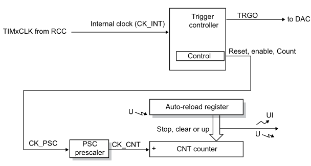
The basic timers TIM6 and TIM7 consist of a 16-bit auto-reload counter driven by a programmable prescaler. They may be used as generic timers for time base generation but they are also specifically used to drive the digital-to-analog converter (DAC). In fact, the timers are internally connected to the DAC and are able to drive it through their trigger outputs.
- 16-bit auto-reload upcounter
- 16-bit programmable prescaler used to divide (also “on the fly”) the counter clock frequency by any factor between 1 and 65535
- Synchronization circuit to trigger the DAC
- Interrupt/DMA generation on the update event: counter overflow
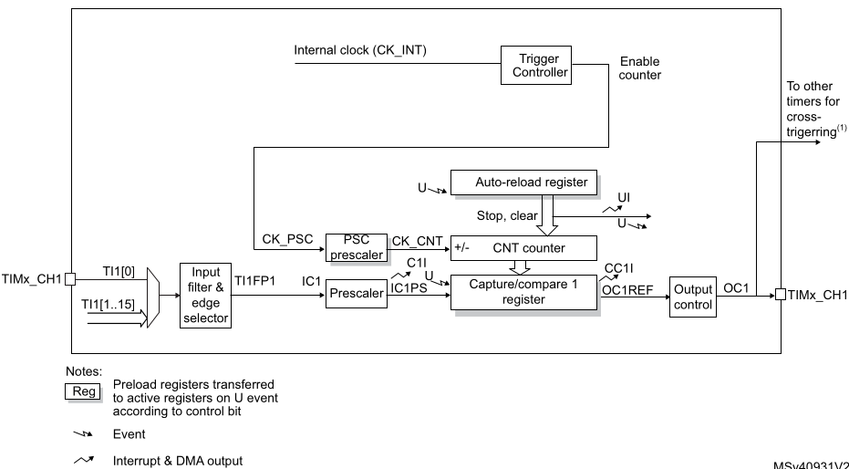
General Purpose Timers 16bits (TIM14)
The TIM14 general-purpose timer consists of a 16-bit auto-reload counter driven by a programmable prescaler. It may be used for a variety of purposes, including measuring the pulse lengths of input signals (input capture) or generating output waveforms (output compare, PWM). Pulse lengths and waveform periods can be modulated from a few microseconds to several milliseconds using the timer prescaler and the RCC clock controller prescalers
- 16-bit auto-reload upcounter
- 16-bit programmable prescaler used to divide the counter clock frequency by any factor between 1 and 65536 (can be changed “on the fly”)
- Independent channel for:
–Input capture
–Output compare
–PWM generation (edge-aligned mode)
–One-pulse mode output - Interrupt generation on the following events:
- Update: counter overflow, counter initialization (by software)
- Input capture
- Output compare
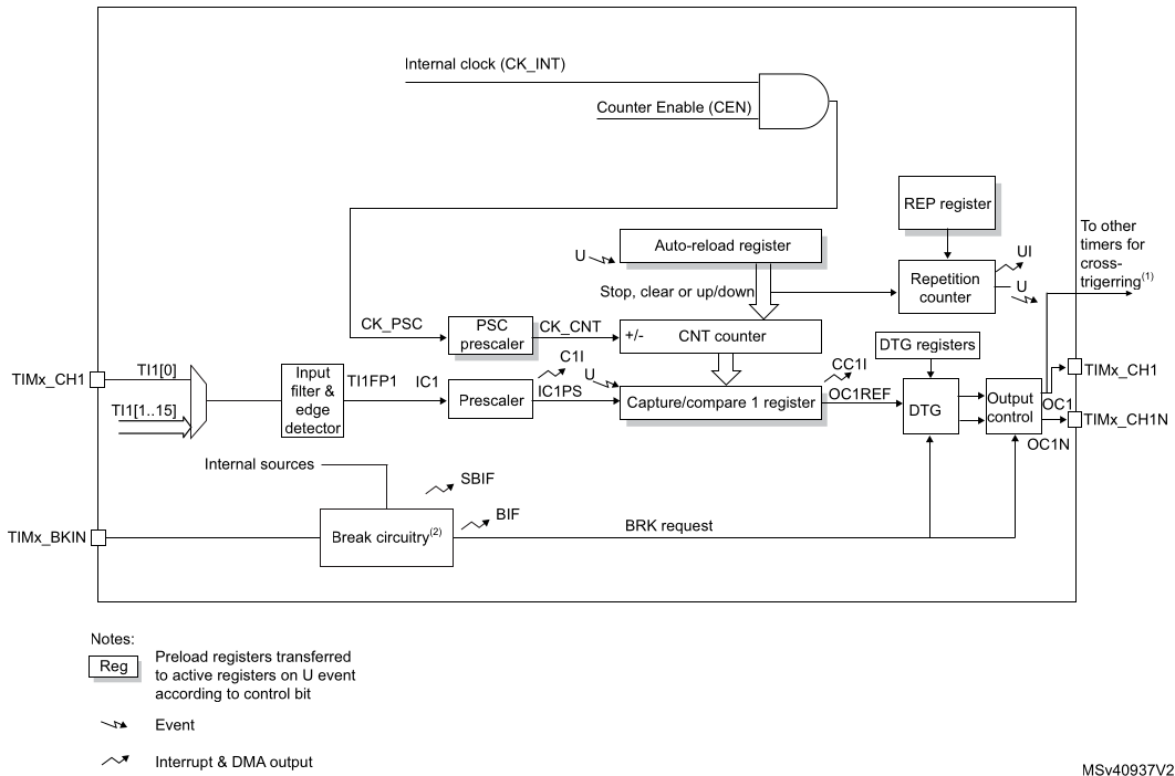
General Purpose Timers 16bits (TIM16/TIM17)
The TIM15/TIM16/TIM17 timers consist of a 16-bit auto-reload counter driven by a programmable prescaler. They may be used for a variety of purposes, including measuring the pulse lengths of input signals (input capture) or generating output waveforms (output compare, PWM, complementary PWM with dead-time insertion). Pulse lengths and waveform periods can be modulated from a few microseconds to several milliseconds using the timer prescaler and the RCC clock controller prescalers.
- 16-bit auto-reload upcounter
- 16-bit programmable prescaler used to divide (also “on the fly”) the counter clock frequency by any factor between 1 and 65535
- One channel for:
–Input capture
–Output compare
–PWM generation (edge-aligned mode)
–One-pulse mode output - Complementary outputs with programmable dead-time
- Repetition counter to update the timer registers only after a given number of cycles of the counter
- Break input to put the timer’s output signals in the reset state or a known state
- Interrupt/DMA generation on the following events:
–Update: counter overflow
–Input capture
–Output compare
–Break input
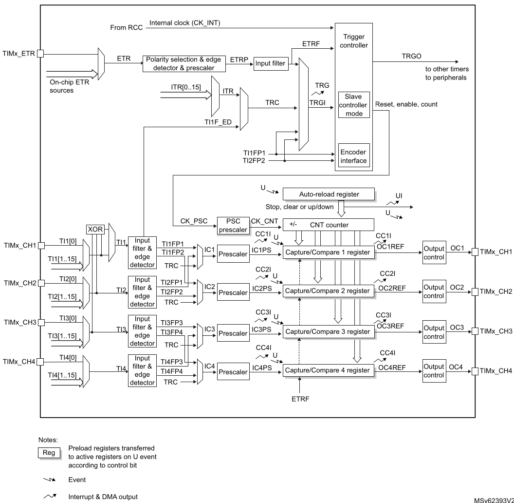
General Purpose Timers 16bits/32bits (TIM2/TIM3/TIM4)
The general-purpose timers consist of a 16-bit/32-bit auto-reload counter driven by a programmable prescaler. They may be used for a variety of purposes, including measuring the pulse lengths of input signals (input capture) or generating output waveforms (output compare and PWM). Pulse lengths and waveform periods can be modulated from a few microseconds to several milliseconds using the timer prescaler and the RCC clock controller prescalers.
- 16-bit (TIM3, TIM4(a)) or 32-bit (TIM2) up, down, up/down auto-reload counter.
- 16-bit programmable prescaler used to divide (also “on the fly”) the counter clock frequency by any factor between 1 and 65535.
- Up to 4 independent channels for:
–Input capture
–Output compare
–PWM generation (Edge- and Center-aligned modes)
–One-pulse mode output - Synchronization circuit to control the timer with external signals and to interconnect several timers.
- Interrupt/DMA generation on the following events:
–Update: counter overflow/underflow, counter initialization (by software or internal/external trigger)
–Trigger event (counter start, stop, initialization or count by internal/external trigger)
–Input capture
–Output compare - Supports incremental (quadrature) encoder and hall-sensor circuitry for positioning purposes
- Trigger input for external clock or cycle-by-cycle current management
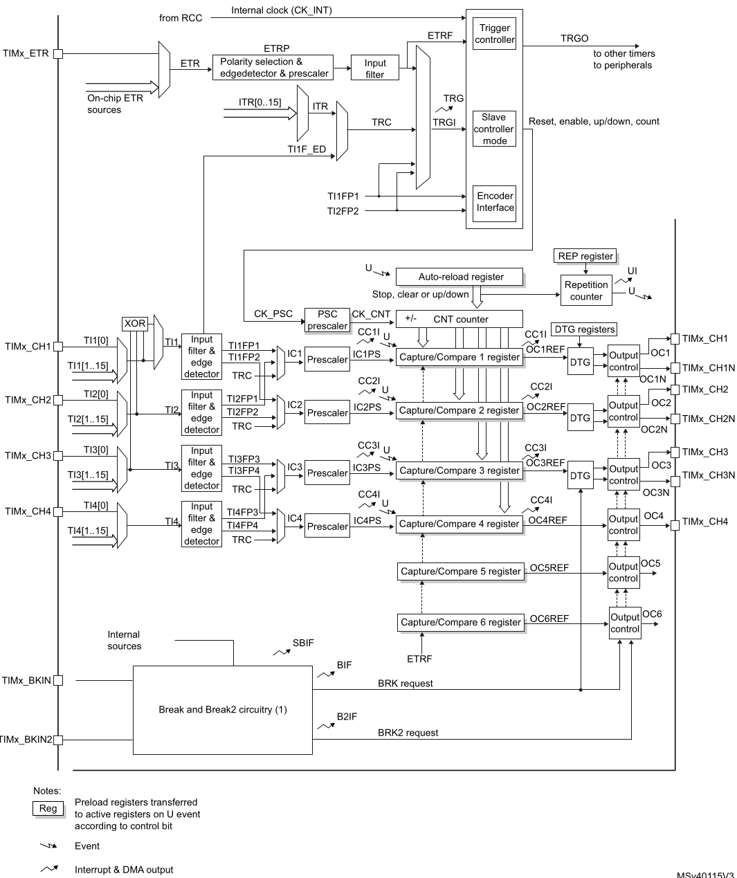
Advanced-control timer (TIM1)
The advanced-control timer (TIM1) consists of a 16-bit auto-reload counter driven by a programmable prescaler. It may be used for a variety of purposes, including measuring the pulse lengths of input signals (input capture) or generating output waveforms (output compare, PWM, complementary PWM with dead-time insertion). Pulse lengths and waveform periods can be modulated from a few microseconds to several milliseconds using the timer prescaler and the RCC clock controller prescalers.
- 16-bit up, down, up/down auto-reload counter.
- 16-bit programmable prescaler allowing dividing (also “on the fly”) the counter clock frequency either by any factor between 1 and 65536.
- Up to 6 independent channels for:
–Input Capture (but channels 5 and 6)
–Output Compare
–PWM generation (Edge and Center-aligned Mode)
–One-pulse mode output - Complementary outputs with programmable dead-time
- Synchronization circuit to control the timer with external signals and to interconnect several timers together.
- Repetition counter to update the timer registers only after a given number of cycles of the counter.
- 2 break inputs to put the timer’s output signals in a safe user selectable configuration.
- Interrupt/DMA generation on the following events:
–Update: counter overflow/underflow, counter initialization (by software or internal/external trigger)
–Trigger event (counter start, stop, initialization or count by internal/external trigger)
–Input capture
–Output compare - Supports incremental (quadrature) encoder and Hall-sensor circuitry for positioning purposes
- Trigger input for external clock or cycle-by-cycle current management
STMicroelectronics Official Video Training
STM32CubeG0 GPIO HAL driver
The code to control the digital ports is located in the following libraries. Make sure the source file is added into the makefile
stm32g0xx_hal_tim.hstm32g0xx_hal_tim.cstm32g0xx_hal_tim_ex.hstm32g0xx_hal_tim_ex.c
In the stm32g0xx_hal_conf.h file, it is necessary to uncomment the define.
#define HAL_TIM_MODULE_ENABLED
Functions
HAL_StatusTypeDef HAL_TIM_Base_Init(TIM_HandleTypeDef *htim);
HAL_StatusTypeDef HAL_TIM_Base_DeInit(TIM_HandleTypeDef *htim);
void HAL_TIM_Base_MspInit(TIM_HandleTypeDef *htim);
void HAL_TIM_Base_MspDeInit(TIM_HandleTypeDef *htim);
HAL_StatusTypeDef HAL_TIM_Base_Start(TIM_HandleTypeDef *htim);
HAL_StatusTypeDef HAL_TIM_Base_Stop(TIM_HandleTypeDef *htim);
HAL_StatusTypeDef HAL_TIM_Base_Start_IT(TIM_HandleTypeDef *htim);
HAL_StatusTypeDef HAL_TIM_Base_Stop_IT(TIM_HandleTypeDef *htim);
HAL_StatusTypeDef HAL_TIM_Base_Start_DMA(TIM_HandleTypeDef *htim, const uint32_t *pData, uint16_t Length);
HAL_StatusTypeDef HAL_TIM_Base_Stop_DMA(TIM_HandleTypeDef *htim);
void HAL_TIM_IRQHandler(TIM_HandleTypeDef *htim);
void HAL_TIM_PeriodElapsedCallback(TIM_HandleTypeDef *htim);
void HAL_TIM_PeriodElapsedHalfCpltCallback(TIM_HandleTypeDef *htim);
Initialization Structure
typedef struct
{
    uint32_t Prescaler;          /*!< Specifies the prescaler value used to divide the TIM clock */
    uint32_t CounterMode;        /*!< Specifies the counter mode */
    uint32_t Period;             /*!< Specifies the period value to be loaded into the active Auto-Reload Register at the next update event */
    uint32_t ClockDivision;      /*!< Specifies the clock division */
    uint32_t RepetitionCounter;  /*!< Specifies the repetition counter value.*/
    uint32_t AutoReloadPreload;  /*!< Specifies the auto-reload preload */
} TIM_Base_InitTypeDef;
Code Snippets
- TIM: Up Counter
- TIM: Down Counter with interrupts
- TIM: Repetition counter
- TIM: Up counter with reload values
- TIM: Two timers timeout
- TIM: Timer trigger another timer count
Exercises
- Use a timer to rotate a led turned on every 200ms, without interrupts
- Complement the previous program with a second timer that trigger the entire rotation every two seconds. Every two seconds the leds should rotate at speed of 100ms
- Write a program that rotates a turned-off LED on port C every 300ms and at the same time flashes the on board LED (connected to A5) every 500ms. Use two TIM timers available on the microcontroller and their timeout interrupts.
- Press a button and have an LED turn on. The LED should turn off 5 seconds later, measured using a TIM timer. Use interrupts to detect the button press and to detect when the 5 seconds have elapsed using a TIM timer.
- Modify the previous program so that the 5 seconds are valid only while the button is pressed. If the button is released before 5 seconds have elapsed, the LED should still turn off.
- Write a program that blinks every 100ms but the led shall be turned off after one second when a button is pressed, use two timers one as Master and the second as slave