
Every microcontroller, regardless of its internal architecture or manufacturer, has General Purpose Input Output ports (GPIO). These peripherals are the easiest to use and represent the first contact of our program with stimuli from the real world.
Digital ports or GPIO ports can function as input or output ports, and this behavior is configured by a special register. Once its behavior is configured, the output data must be written to another special register (if configured as an output), and to read data from the port, it must be accessed in another special register (if configured as an input).
Each port is generally composed of a fixed number of pins, which can be individually configured and controlled. In the case of NXP’s S32K1xx microcontrollers, the ports are composed of up to 32 pins. Each pin can be configured to function as input, output, analog, or have an alternate functionality (serial port, ADC, SPI, etc.)
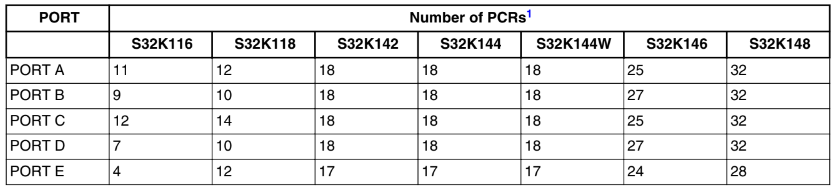
S32K1xx PORT Peripheral
To configure the function mode of each pin there is a special peripheral separated from the GPIOS called PORTs one set of port register for each port identified from letter A to letter E. Before start working with any other peripheral connected to any pins it is necessary to configure its function mode using its corresponding PORT registers.
The PORT module has the following features:
- Pin interrupt
...
- Digital input filter
...
- Port control
• Individual pull control fields with pullup, pulldown, and pull-disable support
• Individual drive strength field supporting high and low drive strength
• Individual input passive filter field supporting enable and disable of the individual input passive filter
• Individual mux control field supporting analog or pin disabled, GPIO, and up to six chip-specific digital functions
• Pad configuration fields are functional in all digital pin muxing modes.
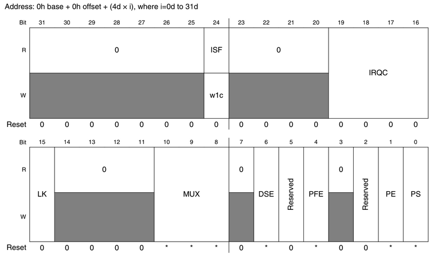
Each pin has its corresponding configuration port called PORT_PCRn, where n represent the pin number. This is not the only register to take into account for port or pin configuration but bits from 8 to 10 can be use to set the pin mode, Up to six modes counting GPIO mode. where can i find the information regarding the pin mode?, well there is an excel file that comes with the user manual called S32K144_IO_Signals_Description_Input_Multiplexing.xlsx
S32K1xx GPIO Peripheral
The GPIO data direction and output data registers control the direction and output data of each pin when the pin is configured for the GPIO function. The GPIO input data register displays the logic value on each pin when the pin is configured for any digital function, provided the corresponding Port Control and Interrupt module for that pin is enabled. Efficient bit manipulation of the general-purpose outputs is supported through the addition of set, clear, and toggle write-only registers for each port output data register.
Features of the GPIO module include:
- Port Data Input register visible in all digital pin-multiplexing modes
- Port Data Output register with corresponding set/clear/toggle registers
- Port Data Direction register
Autosar
It is actually pretty straight forward how to configure and control a Port or a pin in a microcotroller, but you need to keep in mind a couple of concepts established by AUTOSAR,
- PortContainer.- A group of PortPins with no relation amount them ( does not have to be in the same port ), it is up to you to establish how to group all of the pins in use into Port containers.
- PortPin.- This is any pin of the microcotroller, forget about the concept of ports and pins, every pin is identify with its own ID regardless its port,
In the case of this microcontroller family every pin is identified starting from 0 for Pin A0 to up to 160 for E31. If a pin is not presented physically Tresos will signal this with an error. For instance:
- Port A goes from 0 to 31
- Port B goes form 32 to 64
- and so on …
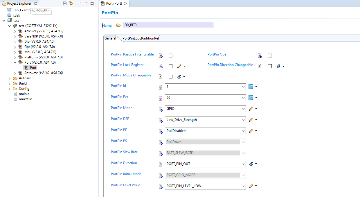
In port driver is where you have to configure the operation mode amount others characteristics determine by AUTOSAR and the micrococontroller characteristics, for instance:
In the case of Dio Driver is even easier since this driver is only in charge of reading and writing the PortPin configured as GPIOS input or outputs. In this case the concept of Port and Pins applied as usual with one detail, every pin is known as DioChannel and a group of one or more are known as DioChannelGroup. To configure a pin to be used by the Dio driver we need first set a DioPort with a value from 0 to 4 where port A is zero and port E is 4, then on each DioPort container you have to set all the channels or group channels you will be using for that particular port, each pin of each port will be identified by a number from 0 to 32 ( and there is no need for configuration )
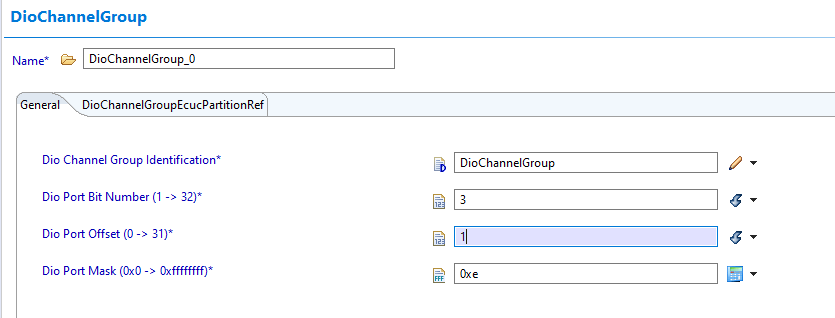
As you may now wonder you can only set a DioChannelGroup in the same DioPort and those pins shall be adyacents, for example: on a given DioPort we set pins from 1 to 4 in the same group, we set 3 Dio Port Bit Number, an offset of one because we don want the pin 0 and a mask 0x0E.
Autosar Interfaces
void Port_Init (const Port_ConfigType ∗ConfigPtr);//Port driver initialization function.
void Port_SetPinDirection (Port_PinType Pin, Port_PinDirectionType Direction);//Port_SetPinDirection.
void Port_SetPinMode (Port_PinType Pin, Port_PinModeType Mode);//Port_SetPinMode.
void Port_GetVersionInfo (Std_VersionInfoType ∗versioninfo);//Port_GetVersionInfo.
void Port_RefreshPortDirection (void);//Port_RefreshPortDirection.

void Dio_GetVersionInfo (Std_VersionInfoType ∗VersionInfo);//Service to get the version information of this module.
Dio_LevelType Dio_ReadChannel (Dio_ChannelType ChannelId);//Returns the value of the specified DIO channel.
void Dio_WriteChannel (Dio_ChannelType ChannelId, Dio_LevelType Level);//Sets the level of a channel.
Dio_LevelType Dio_FlipChannel (Dio_ChannelType ChannelId);//Inverts the level of a channel.
Dio_PortLevelType Dio_ReadPort (Dio_PortType PortId);//Returns the level of all channels of specified port.
void Dio_WritePort (Dio_PortType PortId, Dio_PortLevelType Level);//Sets the value of a port.
Dio_PortLevelType Dio_ReadChannelGroup (const Dio_ChannelGroupType ∗ChannelGroupIdPtr);//This service reads a subset of the adjoining bits of a port.
void Dio_WriteChannelGroup (const Dio_ChannelGroupType ∗ChannelGroupIdPtr, Dio_PortLevelTypeLevel);//Sets a subset of the adjoining bits of a port to the specified levels.
void Dio_MaskedWritePort (Dio_PortType PortId, Dio_PortLevelType Level, Dio_PortLevelType Mask);//DIO Mask write port using mask.
Code Snippets
- DIO: Flip two channels
- DIO: Write a group of channels
- DIO: Rotate a group of channels
- DIO: Reading a channel
Exercises
- Blink the LEDs connected to port C alternately ( turn on LEDs C8, C10, C12, C14 and then 9C, C11, C13, C15 ). Use the initial PortPin Level Value option
- Write a program that rotates a turned-off LED on port C at a speed that is perceptible to the human eye. Define a DioChannelGroup for leds in port C
- Write a program that turns on an LED when a button is pressed and turns it off when the button is released. ( The LED will only turn on when the button is pressed )
- Modify the program number 4 to control the RGB leds with the three buttons, each button shall control each color in the RGB led just like the previous exercise
- Write a program that rotates an LED on port C, but this time with three speeds and three buttons. Each button will activate a different speed.
- Modify exercise 3 so that pressing the button once turns on the LED, and pressing it again turns it off.
- Repeat exercise 5, but this time using only one button and four speeds. Each time the button is pressed, the speed will increase, and when it reaches the last speed, it will start over.
- Modify the previous program using two buttons. Pressing one button will rotate the LEDs from left to right, and pressing the other button will rotate them from right to left.