Measuring time is one of the basic needs within any program, and programs for microcontrollers are no exception. We can generate time intervals by counting instructions of the CPU itself, but this method, although simple, is often inefficient and imprecise.
A peripheral used for measuring time is the Timer, a peripheral that is very common and essential in any microcontroller. Timers "count" clock pulses, which usually come from the same source that feeds the system's CPU frequency. The Timer is typically a simple 8, 16, or 32-bit register that increases its value with each new pulse generated. The pulses that reach the Timer are usually divided or pre-scaled to slow down its counting and obtain longer time intervals. Once its count reaches a maximum value, an overflow event occurs (a flag and/or interruption is activated).
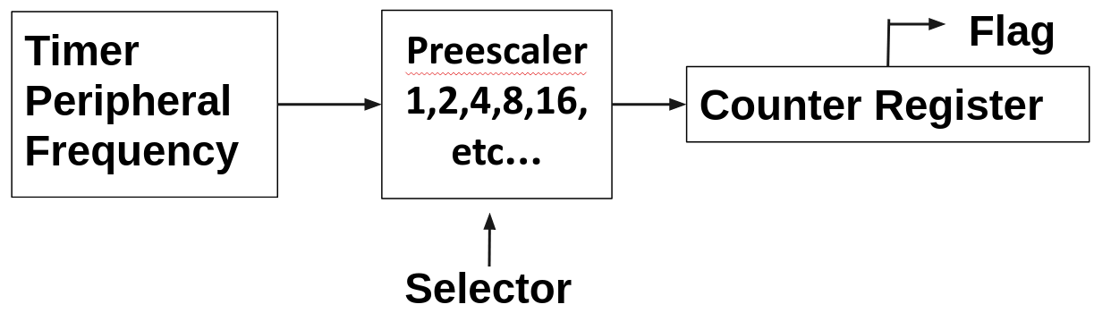
The following diagram is a very basic representation of a typical Timer within a microcontroller, consisting of a counter register, prescaler, and clock source. The clock source provides the input pulses to the Timer, which are then divided or pre-scaled by the prescaler. The resulting pulses are used to increment the value in the counter register. As the counter value increases, it represents the elapsed time. When the counter reaches its maximum value, an overflow event may occur, triggering a flag or interrupt. This basic structure allows the Timer to measure time intervals by counting pulses and provide various timing functionalities in microcontroller applications.
TC37xx System Timer (STM) Peripheral
Infineon AURIX microcontroller posses a system timer on each of its core, It is no the only timer present in the microcontroller but is the most basic one, specially designed to run RTOS or to scheduler a kernel, but can also be use for general purpose. It is an upward free running counter enable after any application reset (there is no need to enable manually, but can be disable sing the CLC register) and has the following features:
- Free-running 64-bit counter
- All 64 bits can be read synchronously
- Different 32-bit portions of the 64-bit counter can be read synchronously
- Flexible service request generation based on compare match with partial STM content
- Counting starts automatically after an Application Reset
- STM registers are reset by an Application Reset if bit ARSTDIS.STMxDIS is cleared. If bit ARSTDIS.STMxDIS is set, the STM registers are not reset by application reset, and are reset by system reset instead.
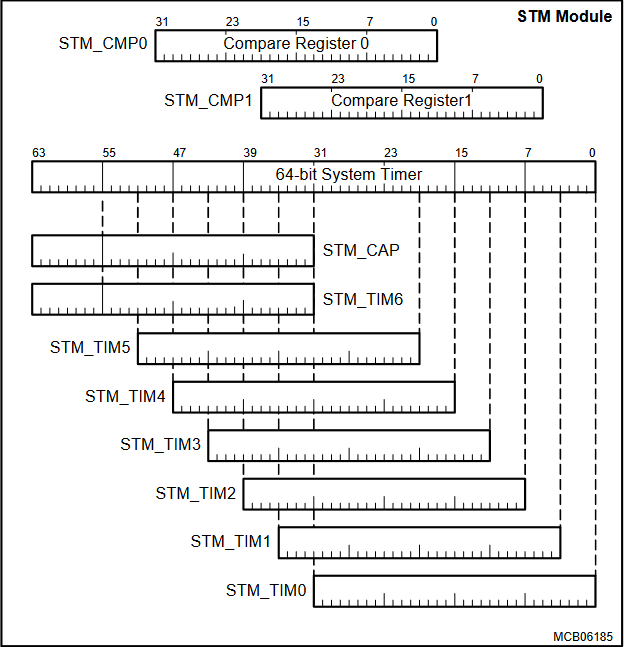
There is no way we can read the 64 bits of the counter in one shot, we need to read the lower 32 bits and then the higher 32 bits usig two load isntructions. Since the timer would continue to count between the two load operations, there is a chance that the two values read are not consistent (due to possible overflow from the low part of the timer to the high part between the two read operations). To avoid this, the STM_CAP register is used to capture the high part of the timer when the low part is read. The STM_CAP register is updated with the high part of the timer when the low part is read. This way, the two values read are consistent.
uint64_t stm_value;

/* Read the lower 32 bits of the STM */
stm_value  = MODULE_STM0->TIM0.U;
/* Read the upper 32 bits of the STM */
stm_value |= ((uint64)MODULE_STM0->CAP.U) << 32;
The STM can also be read in sections from seven registers, TIM0 through TIM6, that select increasingly higher order 32-bit ranges of the STM. These can be viewed as individual 32-bit timers, each with a different resolution and timing range. But for what purpose, lets give an example:
Supose the STM timer is running at fSTM of 100MHz, TIM0 will be counting with a resolution of 10ns, but for TIM1 with a offset of 4 bits (bits 35-4) each count arrive fSTM/16 = 6.25MHz, so the resolution will be 160ns. This way we can have a timer with a resolution of 10ns and another with 160ns, and so on.
With a fSTM = 100MHz

- TIM0: 1/100MHz -> 10ns
- TIM1: 1/(100MHz/16) -> 160ns
- TIM2: 1/(100MHz/256) -> 2.56us
- TIM3: 1/(100MHz/4096) -> 40.96us
- TIM4: 1/(100MHz/65536) -> 655.36us
- TIM5: 1/(100MHz/1048576) -> 10.48576ms
- TIM6: 1/(100MHz/16777216) -> 167.77216ms
Comparator Structure
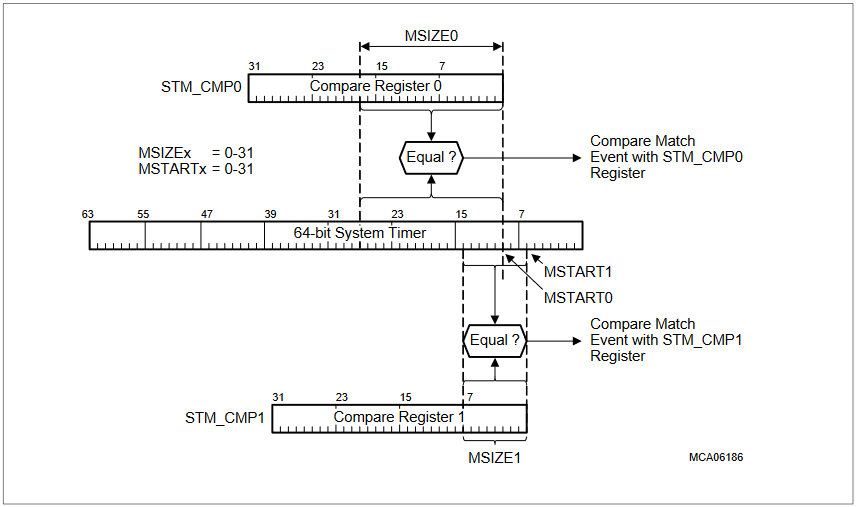
The content of the 64-bit STM can be compared against the content of two compare values stored in the CMP0 and CMP1 registers. Service requests can be generated on a compare match of the STM with the CMP0 or CMP1
registers.
Two parameters are programmable for the compare operation:
- The width of the relevant bits in registers CMP0/CMP1 (compare width MSIZEx) that is taken for the compare operation can be programmed from 0 to 31.
- The first bit location in the 64-bit STM that is taken for the compare operation can be programmed from 0 to
These programming capabilities make compare functionality very flexible. It even makes it possible to detect bit transitions of a single bit n (n = 0 to 31) within the 64-bit STM by setting MSIZE = 0 and MSTART = n
Lets see and example of how to use the STM timer to generate a timeout, we will use the STM0 timer with a resolution of 10ns, and we will set a timeout of 1ms. But instead of counting from the bit 0 we will choose the bit 4, so we will have a resolution of 160ns. to reach the 1ms we need to count 1ms/160ns = 6250, so we will set the CMP0 register to 6250, with only 13 bits needed to represent them.
/* compare only 13 bits starting from bit 4 from Timer */
MODULE_STM0.CMCON.B.MSIZE0  = 13;
MODULE_STM0.CMCON.B.MSTART0 = 4;
/* set the compare value to reach the 1ms*/
MODULE_STM0.CMP0.U = 6250;

/* wait until the timeout has been reach*/
while( MODULE_STM0.ISR.B.CMP0IR == 1 );
The compare operation can trigger an interrupt enabling the CMP0IE bit in the CMCON register, with the possibility to select the two ISR outputs for both CMP0 and CMP1.
/* compare only 13 bits starting from bit 4 from Timer */
MODULE_STM0.CMCON.B.MSIZE0  = 13;
MODULE_STM0.CMCON.B.MSTART0 = 4;

/* enable interrupt and set the CMP0 ISR output */
MODULE_STM0.ISR.B.CMP0EN = 1;
MODULE_STM0.ISR.B.CMP0OS = 0;
/* set the compare value to reach the 1ms*/
MODULE_STM0.CMP0.U = 6250;
It is important to note that the STM timer is a free running counter, so it will continue to count even after the compare operation has been reached, if you want another interrupt to be generated at the same timeout you need to modify the CMP0 register with the new value, in this case:
/*Seudo STM ISR rutine */
void STM0_ISR(void)
{
    /* clear the interrupt flag */
    MODULE_STM0.ISCR.B.CMP0IRR = 1;
    /* set the compare value to reach the 1ms by adding 6250 to previous value*/
    MODULE_STM0.CMP0.U += 6250;
}
There is the possibility to reset the STM timer, this can be done by setting the RST bit in the KRST0 and KRST1 registers, which will reset the timer and re-enable the compare operation. BUT keep in mind the entire STM peripheral is reset!!!, not only the timer counter
/* Only if both Kernel reset bits are set a reset is executed */
MODULE_STM0.KRST0.B.RST = 1;
MODULE_STM0.KRST1.B.RST = 1;

/* Wait until reset is executed */
while (0 == MODULE_STM0.KRST0.B.RSTSTAT);

/* Clear Kernel reset status bit */
MODULE_STM0.KRSTCLR.B.CLR = 1;
Infineon iLLD driver
The code to control the digital ports is located in the following libraries.
IfxStm_Timer.hIfxStm_Timer.cIfxStm.hIfxStm.cIfxStm_cfg.hIfxStm_cfg.c
Include and source paths
Libraries/iLLD/TC37A/Tricore/StmLibraries/iLLD/TC37A/Tricore/Stm/StdLibraries/iLLD/TC37A/Tricore/Stm/Timer
Functions
boolean IfxStm_Timer_init(IfxStm_Timer *driver, const IfxStm_Timer_Config *config);
void IfxStm_Timer_initConfig(IfxStm_Timer_Config *config, Ifx_STM *stm);
boolean IfxStm_Timer_stdIfTimerInit(IfxStdIf_Timer *stdif, IfxStm_Timer *driver);
boolean IfxStm_Timer_setFrequency(IfxStm_Timer *driver, float32 frequency);
float32 IfxStm_Timer_getInputFrequency(IfxStm_Timer *driver);
void IfxStm_Timer_updateInputFrequency(IfxStm_Timer *driver);
Ifx_TimerValue IfxStm_Timer_getPeriod(IfxStm_Timer *driver);
float32 IfxStm_Timer_getResolution(IfxStm_Timer *driver);
void IfxStm_Timer_run(IfxStm_Timer *driver);
boolean IfxStm_Timer_setPeriod(IfxStm_Timer *driver, Ifx_TimerValue period);
void IfxStm_Timer_setSingleMode(IfxStm_Timer *driver, boolean enabled);
boolean IfxStm_Timer_acknowledgeTimerIrq(IfxStm_Timer *driver);
Alter Functions
uint64 IfxStm_get(Ifx_STM *stm);
sint32 IfxStm_getTicksFromMicroseconds(Ifx_STM *stm, uint32 microSeconds);
sint32 IfxStm_getTicksFromMilliseconds(Ifx_STM *stm, uint32 milliSeconds);
float32 IfxStm_getFrequency(Ifx_STM *stm);
void IfxStm_wait(sint64 timeout);
void IfxStm_waitTicks(Ifx_STM *stm, uint32 ticks);
uint32 IfxStm_getLower(Ifx_STM *stm);
uint32 IfxStm_getOffset12Timer(Ifx_STM *stm);
uint32 IfxStm_getOffset16Timer(Ifx_STM *stm);
uint32 IfxStm_getOffset20Timer(Ifx_STM *stm);
uint32 IfxStm_getOffset32Timer(Ifx_STM *stm);
uint32 IfxStm_getOffset4Timer(Ifx_STM *stm);
uint32 IfxStm_getOffset8Timer(Ifx_STM *stm);
uint32 IfxStm_getOffsetTimer(Ifx_STM *stm, uint8 offset);
boolean IfxStm_initCompare(Ifx_STM *stm, const IfxStm_CompareConfig *config);
void IfxStm_initCompareConfig(IfxStm_CompareConfig *config);
uint32 IfxStm_getCompare(Ifx_STM *stm, IfxStm_Comparator comparator);
void IfxStm_increaseCompare(Ifx_STM *stm, IfxStm_Comparator comparator, uint32 ticks);
void IfxStm_updateCompare(Ifx_STM *stm, IfxStm_Comparator comparator, uint32 ticks);
void IfxStm_clearCompareFlag(Ifx_STM *stm, IfxStm_Comparator comparator);
void IfxStm_disableComparatorInterrupt(Ifx_STM *stm, IfxStm_Comparator comparator);
void IfxStm_enableComparatorInterrupt(Ifx_STM *stm, IfxStm_Comparator comparator);
boolean IfxStm_isCompareFlagSet(Ifx_STM *stm, IfxStm_Comparator comparator);
void IfxStm_setCompareControl(Ifx_STM *stm, IfxStm_Comparator comparator, IfxStm_ComparatorOffset offset, IfxStm_ComparatorSize size, IfxStm_ComparatorInterrupt interrupt);
Code Snippets
- STM: Timeout with offset TIM2 timer
- STM: Simple timeout wait with 64 bits
- STM: Delay with Comparators
- STM: Period of times instead of delays
Exercises
- Repeat programs 4, 5, 6, and 7, from previous part, but this time implement them using Concurrent Processes. Use example number three as a base. for instance in exercise number 4 one process will poll the button every 50ms and process number two will also tun every 50ms to turn on and off the led, use a global variable to communicate both process where process buttons send the msg to tun on or off the led on process leds
- Migrate the scheduler with the software timers using the STM timer as the example number three to generate the tick base time, test the scheduler running two task at 100ms and 500ms each one toggling a led. Remove the element timeout from the scheduler control structure because now the scheduler must run forever using a
while(1)or afor(;;) - Repeat the same 4,5, 6 and 7 exercises but this time using he scheduler tasks and/or software timers to run the different process established, also use queues for inter-task communication