Every microcontroller, regardless of its internal architecture or manufacturer, has General Purpose Input Output ports (GPIO). These peripherals are the easiest to use and represent the first contact of our program with stimuli from the real world.
Digital ports or GPIO ports can function as input or output ports, and this behavior is configured by a special register. Once its behavior is configured, the output data must be written to another special register (if configured as an output), and to read data from the port, it must be accessed in another special register (if configured as an input).
Each port is generally composed of a fixed number of pins, which can be individually configured and controlled. In the case of Infineon's AURIX microcontrollers, the ports are composed of up to 16 pins. Each pin can be configured to function as input, output, analog, or have an alternate functionality (serial port, ADC, SPI, etc.).
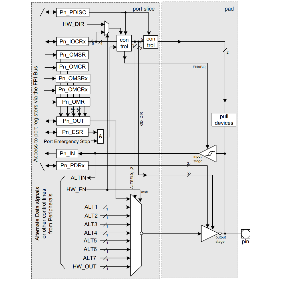
TC37xx Port Peripheral
Depending on its configuration a Port module can have the following features:
- Controls up to 16 port lines.
- Enables SW to control the output of each port line.
- Output modification registers ease clearing, setting and toggling of single port lines and nibbles of port lines without affecting the state of other port lines.
- Enables SW to read the input value of each port line.
- Multiplexes up to 7 alternate functions to each output.
- Supports direct I/O control by a peripheral on a per line granularity.
- Controls pad characteristics of the assigned pads like drive strength, slew rate, pull-up/down, push/pull or open-drain operation, selection of TTL or CMOS/automotive input levels.
- The emergency stop feature allows to switch off the output driver of configurable port lines by SMU or special port pins.
- For pad pairs with LVDS functionality it controls LVDS characteristics and allows switching between LVDS and CMOS modes.
- In packages with reduced pin count the Port module can disable selected pins
Configure the pins
The AURIX Port configuration is quite straightforward, involving minimal complexity. The primary registers required for setup are the IOCRx group (where x can be 0, 4, 8, or 12), which sets the pin mode. The OUT register writes the desired value when the pin is configured as GPIO, and the IN register reads the value from its corresponding pad. So far, it's quite simple. IOCR0 corresponds to pins 0 to 3, IOCR4 to pins 4 to 7, and so forth..
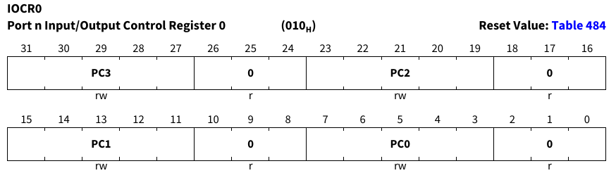
Each pin can be configured with up to five bits to serve as either input or output, including alternate functionalities.
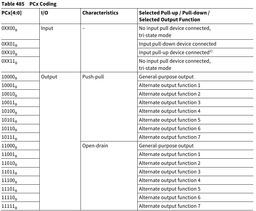
For instance, let’s say we want to configure Port 00 pin 5 as output in GPIO mode Push-Pull
/*se pin 5 in port 00 as output push-pull */
MODULE_P00.IOCR4.B.PC5 = 16;
/*write a value of one*/
MODULE_P00.OUT.B.P5 = 1;

/*toggle pin*/
MODULE_P00.OUT.B.P5 ^= 1;
/*altern mode using OMR register*/
MODULE_P00.OMR.B.PS5 = 1;Setting output strength and voltage levels
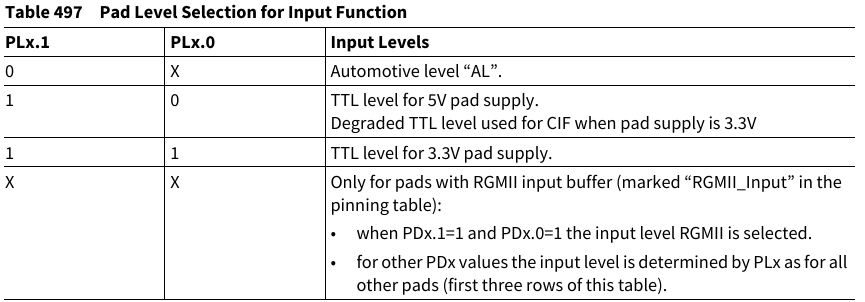
Another thing to keep in mind and configure are the voltage level between 3.3v and 5v and the output driver strength plus slew rate, this can be configured with the registers PDR0 and PDR1. Bits PDx controls the speed grade.
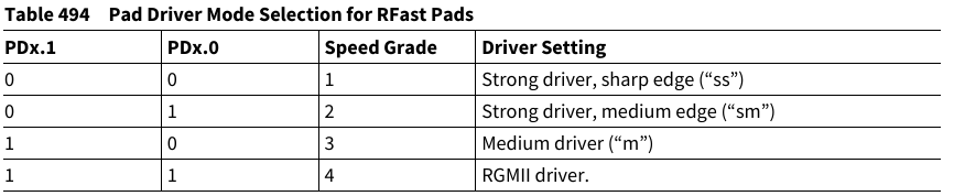
While the bits PLx control the voltage level (5v automotive or TTL and 3.3v TTL)
Here is an example of speed level and voltage level configuration at register level
/*configure strong driver (speed grade 1) */
MODULE_P00.PDR0.B.PD5 = 0;
/*configure Automotive level (5v)*/
MODULE_P00.PDR0.B.PL5 = 0;
Analog pins
Some pins are dedicated solely to analog functions, such as the ADC, while others share both digital and analog functionalities. For these shared pins, there is a special register called the Pin Function Decision Control Register (PDISC). Upon reset, this register contains only zeros, indicating that the analog functions are disabled. If you wish to configure, for instance, pin P00.5, which is connected to Channel 7 of group 9 ADC, you would use this register.
/* set the pin P00.5 as analog */
MODULE_P00.PDISC.B.PDIS5 = 1;
Extra features
Sophisticated microcontroller like the AURIX comes with special features that add interest, such as the emergency stop enabled by the ESR register. When the emergency stop condition is met and activated, the output selection is automatically switched from the alternate output function to the GPIO input function. Another interested feature are the LVDS pins, controlled by the registers LPCRx . Wait, you don’t know what is LVDS?, take a look at the following video LVDS Overview
Infineon iLLD driver
The code to control the digital ports is located in the following libraries.
Ifx_Port_Io.hIfx_Port.hIfx_Port.cIfxPort_PinMap.hIfxPort_PinMap.cIfxPort_cfg.hIfxPort_cfg.c
Include and source paths
Libraries/iLLD/TC37A/Tricore/PortLibraries/iLLD/TC37A/Tricore/Port/IoLibraries/iLLD/TC37A/Tricore/Port/Std
Functions
boolean IfxPort_getPinState(Ifx_P *port, uint8 pinIndex);
void IfxPort_setPinHigh(Ifx_P *port, uint8 pinIndex);
void IfxPort_setPinLow(Ifx_P *port, uint8 pinIndex);
void IfxPort_setPinState(Ifx_P *port, uint8 pinIndex, IfxPort_State action);
void IfxPort_togglePin(Ifx_P *port, uint8 pinIndex);

void IfxPort_setPinModeInput(Ifx_P *port, uint8 pinIndex, IfxPort_InputMode mode);
void IfxPort_setPinModeOutput(Ifx_P *port, uint8 pinIndex, IfxPort_OutputMode mode, IfxPort_OutputIdx index);
void IfxPort_setPinMode(Ifx_P *port, uint8 pinIndex, IfxPort_Mode mode);
void IfxPort_setPinModeLVDS(Ifx_P *port, uint8 pinIndex, IfxPort_Mode pinMode, IfxPort_LvdsConfig *lvds);
void IfxPort_setPinPadDriver(Ifx_P *port, uint8 pinIndex, IfxPort_PadDriver padDriver);
void IfxPort_setPinControllerSelection(Ifx_P *port, uint8 pinIndex);
void IfxPort_setPinFunctionMode(Ifx_P *port, uint8 pinIndex, IfxPort_PinFunctionMode mode);

uint32 IfxPort_getGroupState(Ifx_P *port, uint8 pinIndex, uint16 mask);
void IfxPort_setGroupState(Ifx_P *port, uint8 pinIndex, uint16 mask, uint16 data);
void IfxPort_setGroupModeInput(Ifx_P *port, uint8 pinIndex, uint16 mask, IfxPort_InputMode mode);
void IfxPort_setGroupModeOutput(Ifx_P *port, uint8 pinIndex, uint16 mask, IfxPort_OutputMode mode, IfxPort_OutputIdx index);
void IfxPort_setGroupPadDriver(Ifx_P *port, uint8 pinIndex, uint16 mask, IfxPort_PadDriver padDriver);

boolean IfxPort_disableEmergencyStop(Ifx_P *port, uint8 pinIndex);
boolean IfxPort_enableEmergencyStop(Ifx_P *port, uint8 pinIndex);

Ifx_P *IfxPort_getAddress(IfxPort_Index port);
IfxPort_Index IfxPort_getIndex(Ifx_P *port);
void IfxPort_resetESR(Ifx_P *port, uint8 pinIndex);
void IfxPort_setESR(Ifx_P *port, uint8 pinIndex);
void IfxPort_modifyPinControllerSelection(Ifx_P *port, uint8 pinIndex, boolean mode);
void IfxPort_resetPinControllerSelection(Ifx_P *port, uint8 pinIndex);
Code Snippets
- PORTS: Toggle led
- PORTS: Write Port
- PORTS: Rotate a Pin
- PORTS: Read a single Pin
- PORTS: Read Several Pins
- PORTS: Configure port with Io functions
Exercises
- Blink the LEDs connected to port C alternately (turn on LEDs C0, C2, C4, C6, and then C1, C3, C5, C7).
- Write a program that rotates a turned-off LED on port C at a speed that is perceptible to the human eye.
- Write a program that turns on an LED when a button is pressed and turns it off when the button is released. (The LED will only turn on when the button is pressed.)
- Modify exercise 3 so that pressing the button once turns on the LED, and pressing it again turns it off.
- Write a program that rotates an LED on port C, with three speeds and three buttons. Each button will activate a different speed.
- Repeat exercise 4, but this time using only one button and four speeds. Each time the button is pressed, the speed will increase, and when it reaches the last speed, it will start over.
- Modify the previous program to add two more buttons, pressing one button will rotate the LEDs from left to right, and pressing the other button will rotate them from right to left. One button will remain the same increasing led rotation speed.