In most microcontrollers, the interrupt feature enables a peripheral or an external hardware to send a request to a processor so that the processor can execute a piece of code to service the request. The process involves suspending the current executing task, or wake up from sleep mode, and execute the piece of software code called exception handler to service the request. After the request is serviced, the processor can then resume the previous interrupted code.
Interrupt Flow:
- The peripheral triggers an interrupt on the processor.
- The processor suspends the execution of the program flow. Thread Mode.
- The general-purpose registers of the processor (including the Program Counter) are saved. Stacking.
- The processor executes the interrupt service routine (ISR) of the triggering peripheral. Handler Mode.
- The saved processor registers are retrieved and restored. Unstacking.
- The processor returns to execute the previous program flow.
- The processor knows exactly which instruction to resume as the previous Program Counter was saved prior to the interrupt.
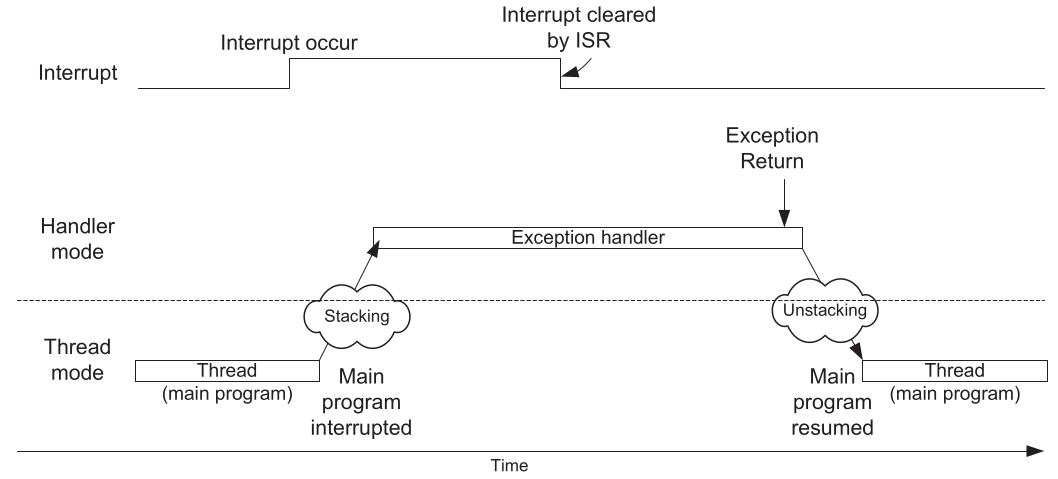
NOTE: Thread mode is the processor running the main program while Handler mode is the processor running the interruption. This is only in Cortex-M terminology
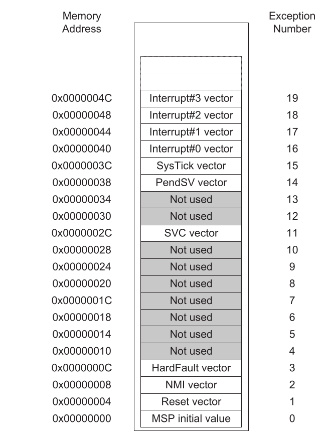
When an interrupt occurs and is accepted by the processor, it needs to determine the entry point or address where the code to be executed starts. A vector table is an array of 32-bit values, and each value stores the address to which the processor should jump according to the occurred interrupt. In the image below, we can observe the vector table located at the beginning of the memory addresses. For example, when a PendSV interrupt occurs, the processor will read the address stored in location 0x0000002C and load it into the program counter to execute the instructions starting from that address.
Cortex-M0plus can handle up to 47 interrupt sources. The interrupts generated by the processor are in the first range, from 1 to 15 (there is no 0). The interrupts numbered from 16 onwards are for the rest of the peripherals, which are implemented by the manufacturers according to their own criteria.
The Nested Vector Interrupt Controller
The NVIC is a programmable unit that allows software to manage interrupts and exceptions. It has a number of memory mapped registers for the following:
- Enabling or disabling of each of the interrupts
- Defining the priority levels of each interrupts and some of the system exceptions
- Enabling the software to access the pending status of each interrupt, including the capability to trigger interrupts by setting pending status in software.
Interrupt Priorities
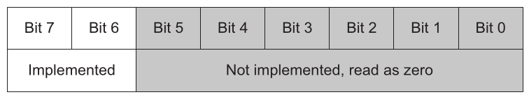
In the Cortex-M0plus processor, each interrupt has a priority level. The priority level affects whether the exception will be carried out, or waits until later (stay in a pending state). processors support three fixed highest priority levels for three of the system exceptions ( Reset, NMI, and HardFault ) and four programmable levels for all other interrupts. The priority level configuration registers are 8-bit wide, but only the two MSBs are implemented.
Interrupts in processors have priorities. When two interrupts occur at the same time, the one with the higher priority will be executed. If the processor is already running an interrupt handler and a new interrupt with a higher priority level occurs, preemption will take place. The running interrupt handler will be temporarily suspended, and the new interrupt handler will be executed. This is known as nested interrupts. Once the new interrupt handler is completed, the previous interrupt handler can resume its execution and eventually return to the main program.
STMicroelectronics Official Video Training
STM32CubeG0 NVIC HAL driver
The code to control the interrupts is located in the following libraries. Make sure the source file is added into the makefile
stm32g0xx_hal_cortex.hstm32g0xx_hal_cortex.c
In the stm32g0xx_hal_conf.h file, it is necessary to uncomment the define.
#define HAL_CORTEX_MODULE_ENABLED
Functions
void HAL_NVIC_SetPriority(IRQn_Type IRQn, uint32_t PreemptPriority, uint32_t SubPriority);
void HAL_NVIC_EnableIRQ(IRQn_Type IRQn);
void HAL_NVIC_DisableIRQ(IRQn_Type IRQn);
void HAL_NVIC_SystemReset(void);
uint32_t HAL_NVIC_GetPriority(IRQn_Type IRQn);
uint32_t HAL_NVIC_GetPendingIRQ(IRQn_Type IRQn);
void HAL_NVIC_SetPendingIRQ(IRQn_Type IRQn);
void HAL_NVIC_ClearPendingIRQ(IRQn_Type IRQn);
Enable Interrupts
The IRQn names can be found at stm32g0b1xx.h in the enum IRQn_Type . The library handle the priority levels with number from 0 to 3, been zero the highest priority level. The third parameter is a sub-priority level but this does not exist in Cortex-M0plus processors.
HAL_NVIC_SetPriority( WWDG_IRQn, 2, 0 );  /*set priority to the lowest level*/
HAL_NVIC_EnableIRQ( WWDG_IRQn );          /*eneable watchdog interrupt*/
Interrup Handler Rutine
The functions linked to interrupt vectors can be written anywhere in the code. However, it is suggested that these functions should be written in the ints.c file for the sake of organization. The library already contains the code that should be placed in each of the interrupt handler functions. These functions can be found in each stm32g0xx_hal_<driver>.h header file, identified as HAL_<driver>_IRQHandler(pointer to driver handler).
/* This function is called when the watchdog interrupt is been triggered, the function shall be declared
by the application using its corresponding name base on the vector table that can be found at startup_stm32g0b1xx.s file */
void WWDG_IRQHandler( void )
{
    /*Inside every ISR a HAL library callback function is called*/
    HAL_WWDG_IRQHandler( hwwdg );
}
Callback Functions
To include custom code when an interrupt occurs, the library uses callback functions that we create according to our application. These callback functions are called by the HAL_xxx_IRQHandlers functions, which in turn are called by the interrupt vectors.
void HAL_WWDG_EarlyWakeupCallback( WWDG_HandleTypeDef *hwwdg )
{
    /*you can place here your application code to run during the ISR,
    there is no need to clean any flag since is already perform by the
    HAL_WWDG_IRQHandler*/
}
Code Snippets
- NVIC: Enable vector interrupt
- NVIC: Interrupt vector and callback
- NVIC: Different Vectors same IRQHandler and same Callback
- NVIC: Same Vector same IRQHandler and same Callback
- NVIC: Same Vector same IRQHandler and different Callbacks
- NVIC: Same Vector different IRQHandler and different Callbacks
- NVIC: Systick Timer
- NVIC: Reconfigure the Systick count
Exercises
- List all the functions that allow us to control interrupts in the processor.
- Analyze and list the interrupt vectors used in EXTI module interrupts.
- Using interrupts on both edges, write a program that turns on an LED on the board when a button is pressed and turns it off when released. (The LED should only turn on when the button is pressed.)
- Create a program that monitors three buttons (using interrupts) and rotates a turned-off LED at different speeds when each button is pressed.
- Write a program that rotates a turned-off LED on port C every 300ms and at the same time flashes the on board LED (connected to A5) every 500ms. Use two TIM timers available on the microcontroller and their timeout interrupts.
- Press a button and have an LED turn on. The LED should turn off 5 seconds later, measured using a TIM timer. Use interrupts to detect the button press and to detect when the 5 seconds have elapsed using a TIM timer.
- Modify the previous program so that the 5 seconds are valid only while the button is pressed. If the button is released before 5 seconds have elapsed, the LED should still turn off.
- Repeat programs 4, 5, 6, and 7, but this time do not use any interrupts. Implement them using . Note that you will still need to use the SysTick timer interrupt, but it is already controlled by the library. Use example number 3 as a base.