Every microcontroller, regardless of its internal architecture or manufacturer, has General Purpose Input Output ports (GPIO). These peripherals are the easiest to use and represent the first contact of our program with stimuli from the real world.
Digital ports or GPIO ports can function as input or output ports, and this behavior is configured by a special register. Once its behavior is configured, the output data must be written to another special register (if configured as an output), and to read data from the port, it must be accessed in another special register (if configured as an input).
Each port is generally composed of a fixed number of pins, which can be individually configured and controlled. In the case of ST's stm32g0xx microcontrollers, the ports are composed of up to 16 pins. Each pin can be configured to function as input, output, analog, or have an alternate functionality (serial port, ADC, SPI, etc.).
Characteristics:
- Up to 16 pins per port
- Independent input and output registers
- Push-pull or open-drain outputs
- Outputs with pull-up or pull-down
- Sampling speed selector
- Floating, pull-up/pull-down or analog inputs
- Up to 8 alternate functions per pin
- Set and reset options for fast write operations of up to two clock cycles.
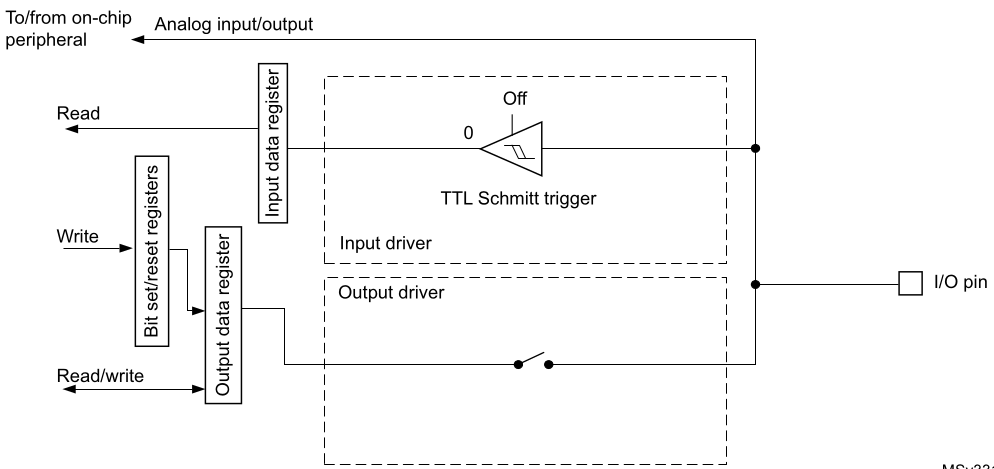
Port basic structure
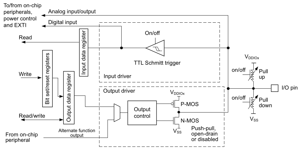
Each port bit of the general-purpose I/O (GPIO) ports can be individually configured by software in several modes:
- Input floating
- Input pull-up
- Input-pull-down
- Analog
- Output open-drain with pull-up or pull-down capability
- Output push-pull with pull-up or pull-down capability
- Alternate function push-pull with pull-up or pull-down capability
- Alternate function open-drain with pull-up or pull-down capability
Functionality
Additionally, each pin can have a maximum operating speed, which determines how quickly it can respond to external stimuli or change its state. The GPIOx_OSPEEDR register configures up to four possible speeds: Very Low Speed, Low Speed, High Speed, and Very High Speed. The speed can be selected individually for each pin in the GPIO port.
The GPIO ports can operate in either push-pull or open-drain configuration. In push-pull, both high and low signals are driven actively by the microcontroller. In open-drain, only the low signal is actively driven, and the high signal is left floating or pulled up externally. The configuration is set in the GPIOx_OTYPER register.
Each pin can also have an internal pull-up or pull-down resistor enabled. The pull-up resistor connects the pin to VDD and the pull-down resistor connects it to ground. This can be useful for keeping the pin in a known state when there is no external signal. The configuration is set in the GPIOx_PUPDR register.
Finally, the GPIO ports have options for fast set and reset operations, which allow the state of multiple pins to be changed simultaneously with minimal delay. These operations can be performed using the GPIOx_BSRR register.
Note: Refer to the device datasheet for the frequency specifications and the power supply and load conditions for each speed.
Input configuration
When the I/O port is programmed as input:
- The output buffer is disabled
- The Schmitt trigger input is activated
- The pull-up and pull-down resistors are activated depending on the value in the GPIOx_PUPDR register
- The data present on the I/O pin are sampled into the input data register every AHB clock cycle
- A read access to the input data register provides the I/O state
Output Configuration
When the I/O port is programmed as output:
- The output buffer is enabled:
- Open drain mode: A “0” in the Output register activates the N-MOS whereas a “1” in the Output register leaves the port in Hi-Z (the P-MOS is never activated)
- Push-pull mode: A “0” in the Output register activates the N-MOS whereas a “1” in the Output register activates the P-MOS
- The Schmitt trigger input is activated
- The pull-up and pull-down resistors are activated depending on the value in the GPIOx_PUPDR register
- The data present on the I/O pin are sampled into the input data register every AHB clock cycle
- A read access to the input data register gets the I/O state
- A read access to the output data register gets the last written value
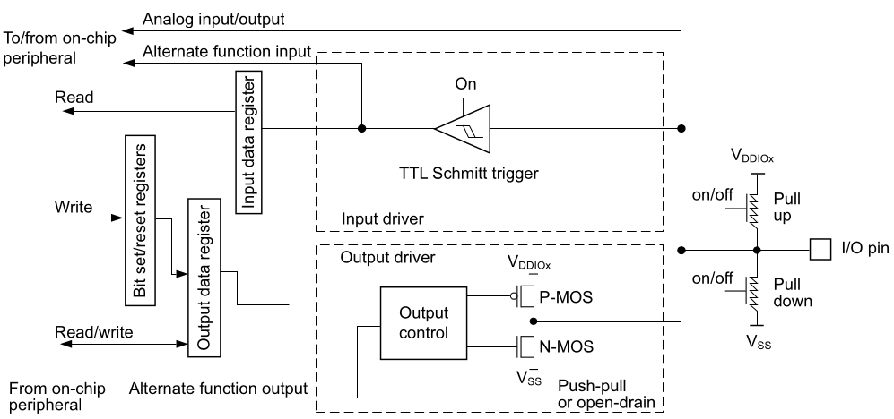
Alternate function configuration
When the I/O port is programmed as alternate function:
- The output buffer can be configured in open-drain or push-pull mode
- The output buffer is driven by the signals coming from the peripheral (transmitter enable and data)
- The Schmitt trigger input is activated
- The weak pull-up and pull-down resistors are activated or not depending on the value in the GPIOx_PUPDR register
- The data present on the I/O pin are sampled into the input data register every AHB clock cycle
- A read access to the input data register gets the I/O state
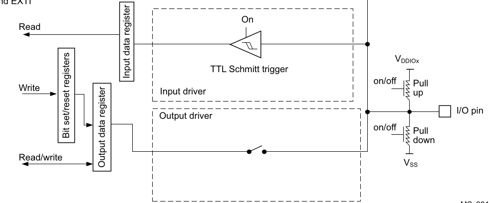
Analog configuration
When the I/O port is programmed as analog configuration:
- The output buffer is disabled
- The Schmitt trigger input is deactivated, providing zero consumption for every analog value of the I/O pin. The output of the Schmitt trigger is forced to a constant value (0).
- The weak pull-up and pull-down resistors are disabled by hardware
- Read access to the input data register gets the value “0”
STMicroelectronics Official Video Training
STM32CubeG0 GPIO HAL driver
The code to control the digital ports is located in the following libraries. make sure the source file is added into the makefile
stm32g0xx_hal_gpio.hstm32g0xx_hal_gpio.cstm32g0xx_hal_gpio_ex.h
In the stm32g0xx_hal_conf.h file, it is necessary to uncomment the define.
#define HAL_GPIO_MODULE_ENABLED
Functions
GPIO_PinState     HAL_GPIO_ReadPin(GPIO_TypeDef *GPIOx, uint16_t GPIO_Pin);
void              HAL_GPIO_WritePin(GPIO_TypeDef *GPIOx, uint16_t GPIO_Pin, GPIO_PinState PinState);
void              HAL_GPIO_TogglePin(GPIO_TypeDef *GPIOx, uint16_t GPIO_Pin);
HAL_StatusTypeDef HAL_GPIO_LockPin(GPIO_TypeDef *GPIOx, uint16_t GPIO_Pin);
void              HAL_GPIO_EXTI_IRQHandler(uint16_t GPIO_Pin);
void              HAL_GPIO_EXTI_Rising_Callback(uint16_t GPIO_Pin);
void              HAL_GPIO_EXTI_Falling_Callback(uint16_t GPIO_Pin);
Initialization Structure
typedef struct
{
    uint32_t Pin;       /*pin(s)*/
    uint32_t Mode;      /*function mode*/
    uint32_t Pull;      /*pin terminal resistor*/
    uint32_t Speed;     /*operation frequency*/
    uint32_t Alternate; /*Altern mode*/
} GPIO_InitTypeDef;
Code Snippets
- GPIOS: Toggle two leds
- GPIOS: Write am 8 bit port
- GPIOS: Rotate a pin
- GPIOS: Read single pin
- GPIOS: Read Several pins
- GPIOS: Read pins as a port
- GPIOS: Read pin with interrupts
- GPIOS: Read pins with interrupts
- GPIOS: Read pins with different interrupts
Exercises:
it is not necessary to use interrupts at this point
- Blink the LEDs connected to port C alternately ( turn on LEDs C0, C2, C4, C6, and then C1, C3, C5, C7 and so on).
- Write a program that rotates a turned-off LED on port C at a speed that is perceptible to the human eye.
- Write a program that turns on an LED when a button is pressed and turns it off when the button is released. ( The LED will only turn on when the button is pressed )
- Write a program that rotates an LED on port C, but this time with three speeds and three buttons. Each button will activate a different speed.
- Modify exercise 4 so that pressing the button once turns on the LED, and pressing it again turns it off.
- Repeat exercise 5, but this time using only one button and four speeds. Each time the button is pressed, the speed will increase, and when it reaches the last speed, it will start over.
- Modify the previous program using two buttons. Pressing one button will rotate the LEDs from left to right, and pressing the other button will rotate them from right to left.