Let’s do something more interesting and complex. In this example a Task Event is triggered when the message “turn on” is received through UART, this task event will turn on a led on GPIOC pin 0.
#include "bsp.h"
#include "RTOS.h"
#define EVENT0 (1u << 0) // Bit 0 of the event bit mask
#define EVENT1 (1u << 1) // Bit 1 of the event bit mask
uint8_t RxBuffer[ 10 ]; //buffer for message received
UART_HandleTypeDef UartHandle; //UART control structure
static OS_STACKPTR int HPStack[128], LPStack[128]; // Task Stack
static OS_TASK TaskCB0, TaskCB1; // Task control structure
static void Task0(void);
static void Task1(void);
int main( void )
{
OS_Init(); // Initialize embOS (must be first)
HAL_Init();
OS_InitHW(); // Initialize Hardware for embOS
OS_TASK_CREATE( &TaskCB0, "EVENT TASK", 100, Task0, HPStack ); // Creating the task.
OS_TASK_CREATE( &TaskCB1, "UART TASK", 50, Task1, LPStack ); // Creating the task.
OS_Start(); // Start multitasking
return 0u;
}
static void Task0(void)
{
__HAL_RCC_GPIOC_CLK_ENABLE(); // Enable GPIOC Clock
OS_TASKEVENT MyEvents; // This is our bit mask whith a 32 bits width
GPIO_InitTypeDef GPIO_InitStruct;
GPIO_InitStruct.Mode = GPIO_MODE_OUTPUT_PP;
GPIO_InitStruct.Speed = GPIO_SPEED_FREQ_LOW;
GPIO_InitStruct.Pull = GPIO_NOPULL;
GPIO_InitStruct.Pin = GPIO_PIN_0;
HAL_GPIO_Init( GPIOC, &GPIO_InitStruct );
while(1)
{
MyEvents = OS_TASKEVENT_GetBlocked( EVENT0 | EVENT1 ); // Wait for event bits 0 or 1
if(MyEvents & EVENT0 )
{ // If the bit 0 is set, the EVENT0 is triggered and the pin 0 is SET
SEGGER_SYSVIEW_PrintfHost( "EVENT 0" );
HAL_GPIO_WritePin( GPIOC, GPIO_PIN_0, SET );
}
else if( MyEvents & EVENT1 ){ // If the bit 1 is set, the EVENT1 is triggered and the pin 0 is RESET
SEGGER_SYSVIEW_PrintfHost( "EVENT 1" );
HAL_GPIO_WritePin( GPIOC, GPIO_PIN_0, RESET );
}
}
}
static void Task1(void)
{
/*UART configuration options for module USART2, 9600 baudrate,
8bits, 1 stop bit, no parity, no flow control, and 8 bit lenght */
UartHandle.Instance = USART2;
UartHandle.Init.BaudRate = 9600;
UartHandle.Init.WordLength = UART_WORDLENGTH_8B;
UartHandle.Init.StopBits = UART_STOPBITS_1;
UartHandle.Init.Parity = UART_PARITY_NONE;
UartHandle.Init.HwFlowCtl = UART_HWCONTROL_NONE;
UartHandle.Init.Mode = UART_MODE_TX_RX;
UartHandle.Init.OverSampling = UART_OVERSAMPLING_16;
/*init UART2 with previous paramters*/
HAL_UART_Init( &UartHandle );
while(1)
{
if( HAL_UART_Receive( &UartHandle, &RxBuffer[0], 7, 5000 ) == HAL_OK ){ // If a 7 bytes message is received the program will enter in this conditional
/*compare the four bytes received against the string "turn on"*/
if( memcmp( "turn on", RxBuffer, sizeof("turn on") ) == 0 )
{
HAL_UART_Transmit( &UartHandle,(uint8_t *)"LED on\r\n", 8, 500 );
OS_TASKEVENT_Set(&TaskCB0, EVENT0); // Triggering EVENT0
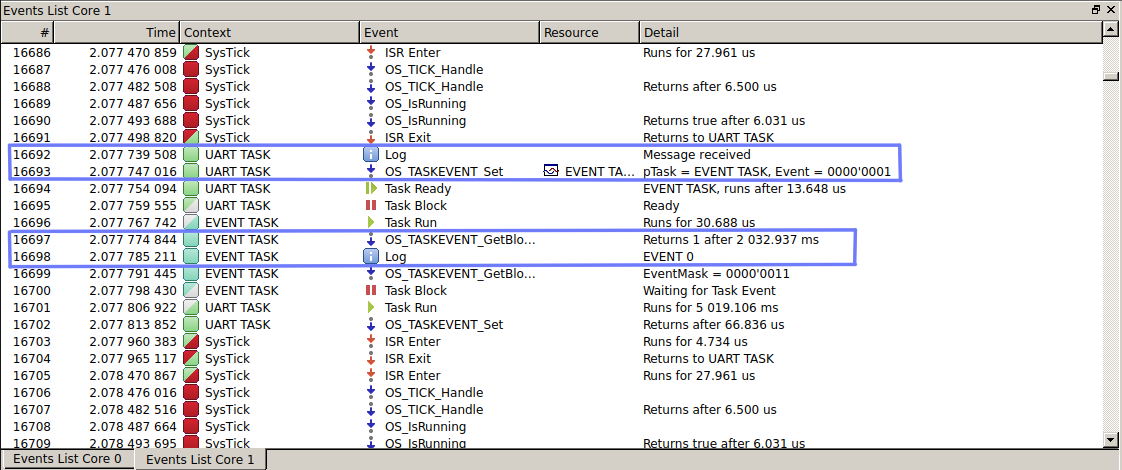
SEGGER_SYSVIEW_PrintfHost( "Message received" );
}
}
else
{
/*If during the 10 seocnds we didn't receive anything, let s send back a "Timeout mesage" and RESET the LED*/
HAL_UART_Transmit( &UartHandle,(uint8_t *)"LED off\r\n", 9, 500 );
HAL_UART_Transmit( &UartHandle,(uint8_t *)"Timeout\r\n", 9, 500 );
OS_TASKEVENT_Set(&TaskCB0, EVENT1); // Triggering EVENT1
SEGGER_SYSVIEW_PrintfHost( "No messages" );
}
}
}msps.c
/*The function is called from HAL_UART_Init at the very beginning
and allows us to set the pins to be used as serial port*/
void HAL_UART_MspInit( UART_HandleTypeDef *huart )
{
    GPIO_InitTypeDef GPIO_InitStruct; /*gpios init structure*/

    __HAL_RCC_USART2_CLK_ENABLE();    /*enable usart2 clock*/
    __HAL_RCC_GPIOA_CLK_ENABLE();     /*eneable port A clock */

    /*set pin 2(tx) and pin 3(rx) from port A in altern mode usart2
    the altern mode info can be found in device datasheet*/
    GPIO_InitStruct.Pin   = GPIO_PIN_2 | GPIO_PIN_3;
    GPIO_InitStruct.Mode  = GPIO_MODE_AF_PP;
    GPIO_InitStruct.Pull  = GPIO_NOPULL;
    GPIO_InitStruct.Speed = GPIO_SPEED_FREQ_HIGH;
    GPIO_InitStruct.Alternate = GPIO_AF1_USART2;
    /*apply configuration configuracion*/
    HAL_GPIO_Init( GPIOA, &GPIO_InitStruct );
}
SYSTEMVIEW
Build and flash the program and then run systemview.
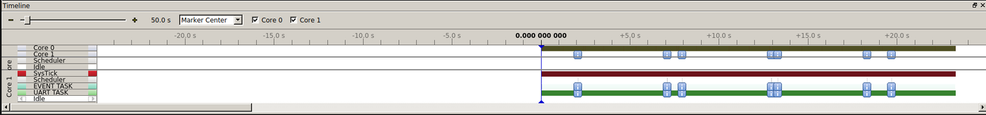
Look at the timeline. Notice how the “EVENT TASK” runs only when a message arrives.
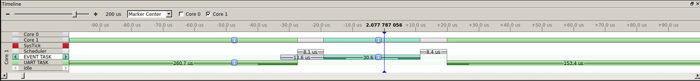
Looking closer you can see the moment in which the message arrives and therefore the "EVENT 0" is triggered thus executing the task and the same thing happens if there’s no message within 5 seconds.